IC-7410 Rig Control Program and Soft66LC4 (4)

soft66waterfall

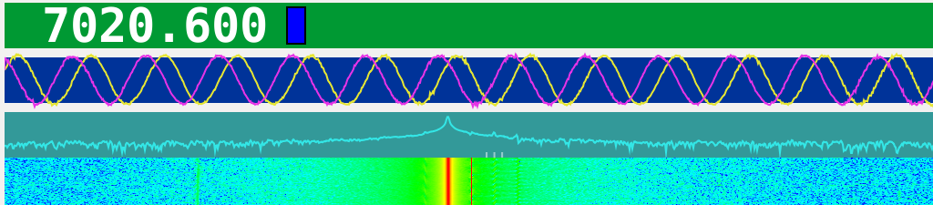
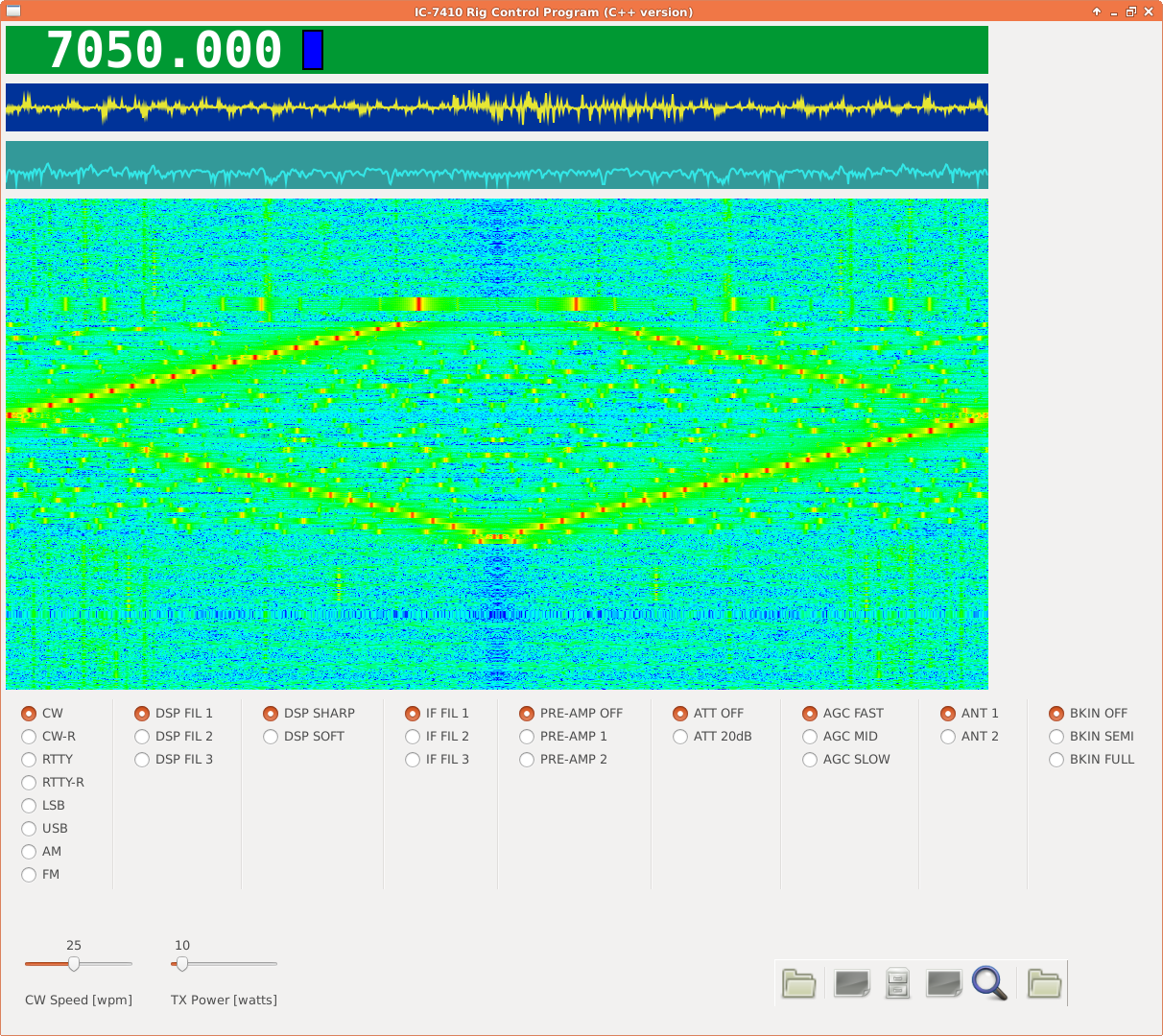
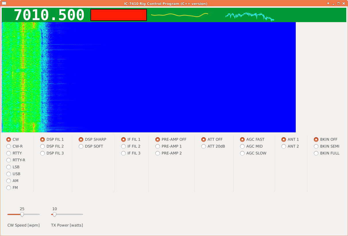
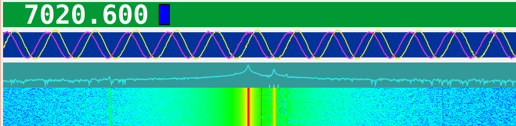
The IQ signals from Soft66LC4 is not saturated this time with the RF signal at LO+600Hz.

The DC is now at the center of the waterfall indicated by a thin red line. Since the IQ signals are inverted (actually they are QI instead of IQ), positive frequencies are plotted on the left half of the display. The bright red line is the actual RF signal, and the yellow line on the right half is its image.

soft66iqt

The gains for the IQ channels differs slightly.

soft66xy

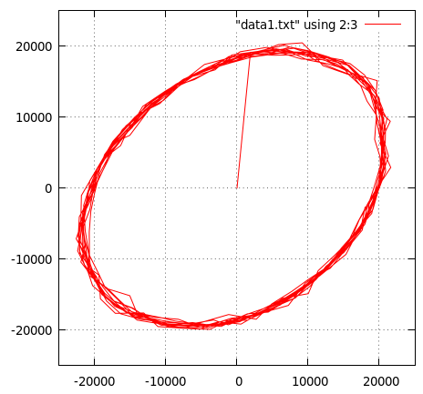
And the phase difference for the IQ signals is not 90 degrees as you can see.

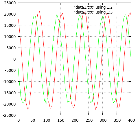
If we receive an RF signal which is 600Hz higher than that of LO, ideally we should have IQ signals which are cos(600Hz) and sin(600Hz), respectively, with the same amplitude and exactly with 90 degrees phase difference.

Unfortunately, we have some errors in the circuit, and we will have some_gain*sin(600Hz+some_phase) as a Q signal. (Without loss of generality, we can assume that the I signal is always perfect for our current purposes.)

So the problem is how we can recover the Q signal with some_gain to be 1.0, and some_pahse to be 0. Since we usually do only linear operations, what we can do is limited to compute the linear combination of the obtained IQ signals, namely, Q_adjusted = C1 * I_obtained + C2 * Q_obtained, where we assume both C1 and C2 are the frequency independent constants.

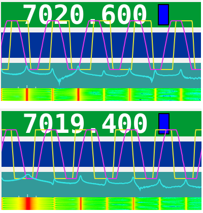
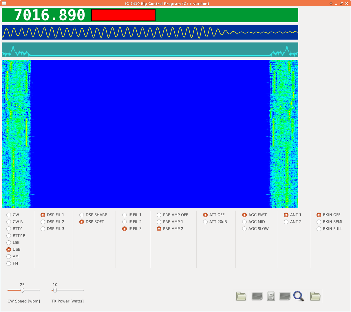
In our previous example, if we set, by observations, C1 to be -0.32 and C2 to be 1.14, and if we give DC offset of +400 to the I channel, we will get a nice circle as is shown below.

soft66xy2

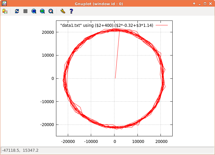
If you want to be more theoretical, you can fiddle with the equations such as (I’,Q’)=matrix([1,0], [a,b]) (I,Q), and (I,Q)=matrix([1,0],[-a/b, 1/b])(I’,Q’), etc., but the conclusion is the same.

    if(channels == 2) {
      for(int i =0; i < NFFT; i+=2) {
    	  audio_signal[i]   = samples[i] + 400.0;
    	  audio_signal[i+1] = -0.32*samples[i] + 1.14*samples[i+1];
      }
    }

With the above code, the image at -600Hz, which is on the right half of the display due to the inverted IQ signals, is much more suppressed.

soft66waterfall2

2014 CQ WW DX CW Log Check Report

Contest:    2014 CQ WW DX CONTEST CW
Call:       JH1OOD
Category:   Single Op 28 MHz Low Power

** Summary **
      6 Claimed QSO before checking (does not include duplicates)
       5 Final   QSO after  checking reductions
   16.7% Error Rate based on claimed and final qso counts
       1 (16.7%) exchanges copied incorrectly

** Incorrect Exchange Information **
28028 CW 2014-11-30 0311 JH1OOD          25 KH7XX           13 correct   31

**  Multipliers by band  **
10M multiplier total 10
HS    KH0   KH6   LU    ZL    
 13 26 27 31 32

Again! It reveals that I can not remember CQ zones, and that I am so careless, and…

IC-7410 Rig Control Program and Soft66LC4 (3)

soft66IQ

The LO of Soft66LC4 is set to 7020kHz, and the RF signal from IC-7410 is either at +600Hz or at -600Hz.

The captured analog IQ-signals are highly saturated with somewhat higher gain with the I-channel (yellow) than with the Q-channel (purple).

IC-7410 Rig Control Program and Soft66LC4 (2)

soft66waterfall2

This waterfall is generated using the baseband I-Q signals from Soft66LC4. You have much wider bandwidth than is possible with the audio signal from IC-7410.

Frequency control of Soft66LC4 is not implemented yet, so CLI is being used now.

% soft66-control -t 7020
Tuned to 7020.000kHz

% sprigmm /dev/ttyUSB0 hw:0,0 48000 2

IC-7410, terminated with a dummy load, is used as a signal source, and the frequency is changed from 7000kHz to 7050kHz with a step size of 1kHz. The DC is on the right (or left) edge of the waterfall. Side band suppression is not very good, because neither the gain nor the phase is adjusted for I-Q signals, but you can see which is the image.

soft66waterfall3

This with IC-7410. The bandwidth of the audio signal is 3.0 kHz with USB mode. The waterfall is symmetrical because the incoming signal is real, and only the amplitude of the FFTed signal is displayed.

% sprigmm /dev/ttyUSB0 hw:2,0 32000 1

Note that the FFT size is now 1024 instead of previous 4096.

IC-7410 Rig Control Program and Soft66LC4

/* for IC-7410 */
unsigned int rate = 32000;      /* stream rate */
unsigned int channels = 1;      /* count of channels */

/* for Soft66LC4 via PC soundcard */
//unsigned int rate = 48000;    /* stream rate */
//unsigned int channels = 2;    /* count of channels */

Since IC-7410 and Soft66LC4 can be controlled simultaneously from HDSDR (see IC-7410 and Soft66LC4), it may be desirable to do the same thing with my program.

The intention is to display a wideband waterfall with Soft66LC4, and, on clicking, to tune IC-7410 for transmission.

% soft66-control -l
Bus 002 device 003:
  Manufacturer: FTDI
  Description:  FT232R USB UART
  Serial no.:   A700eOYJ
1 device found

% lsusb
Bus 002 Device 003: ID 0403:6001 Future Technology Devices International, Ltd FT232 USB-Serial (UART) IC