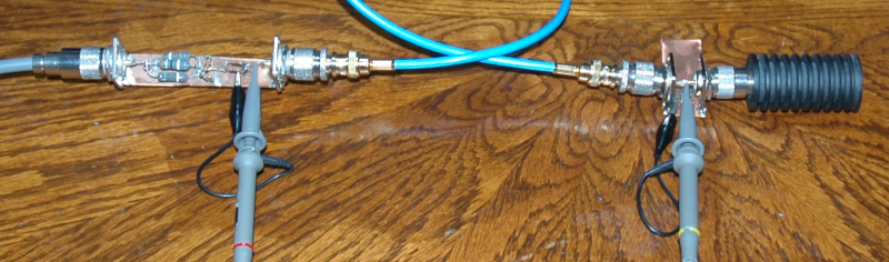
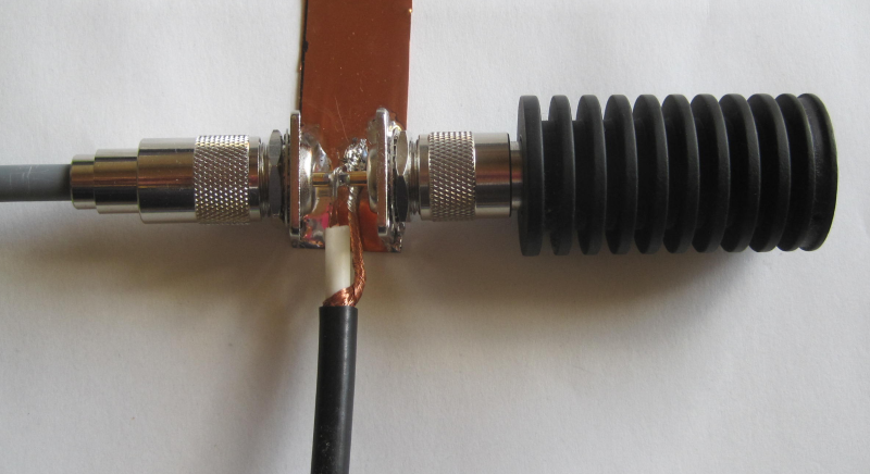
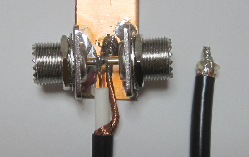
Now with my antenna cable, 20m of 5D-2V.

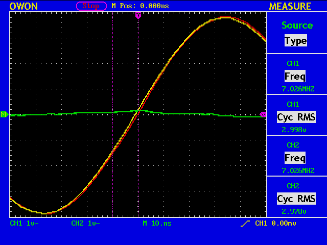
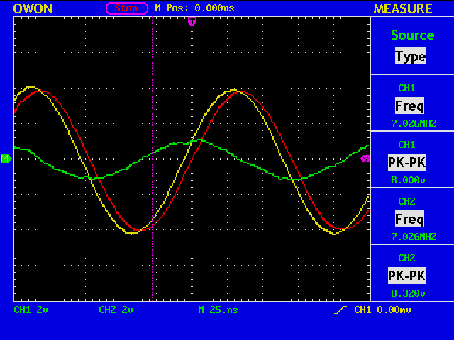
First, both channels at the dummy load.
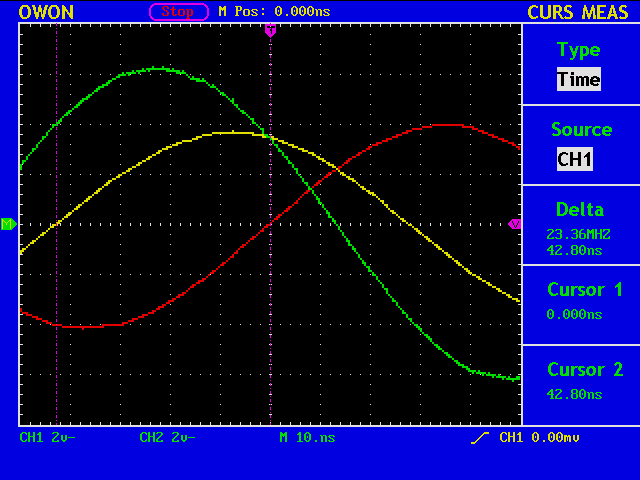
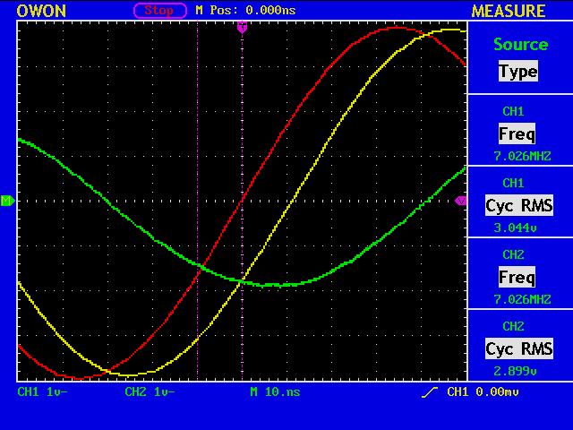
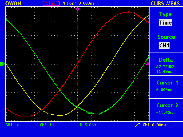
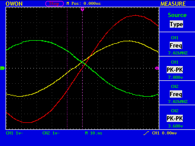
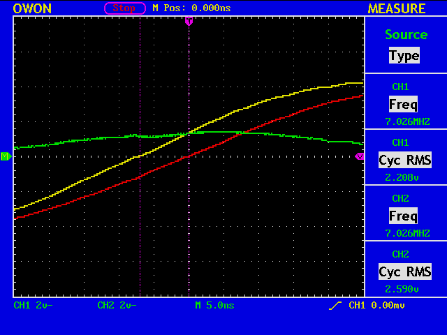
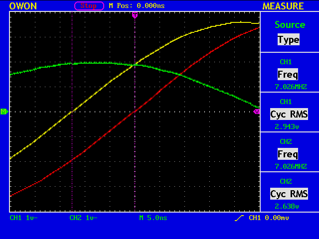
Then, the delay is measured to be -42.80nS at 7.026MHz (T=142.32nS), which means 99.52nS of delay.
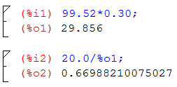
Since the physical length of the cable is 20m, the velocity factor is computed to be 0.67, which is quite a reasonable value.
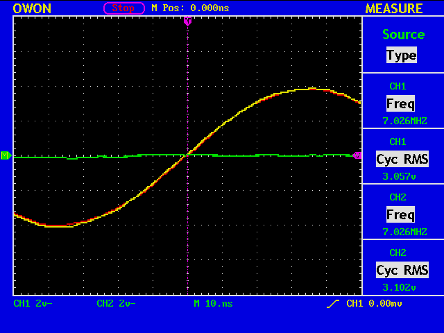
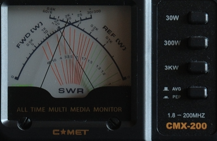
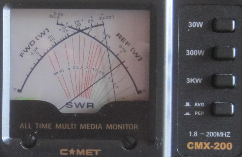
The impedance bridge shows that the SWR value is almost 1.0, because the 20m cable is terminated with a dummy load.
The voltage difference at the impedance bridge and at the dummy load is due to the cable loss of 20m.
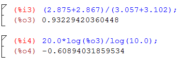
The measured loss is around 0.61dB. Note that the loss of 5D-2V cables at 10MHz is 26dB/km or 0.52dB/20m.
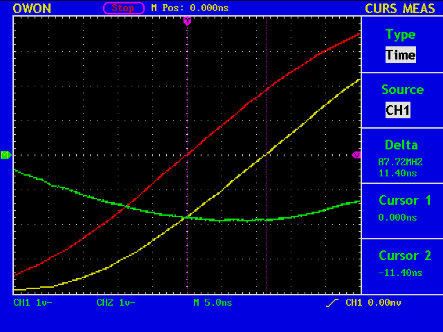
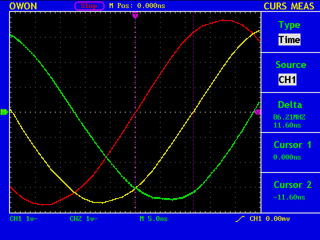
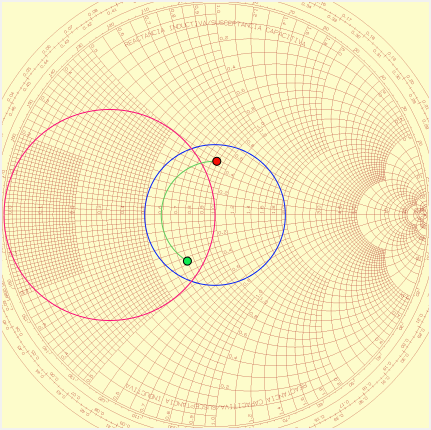
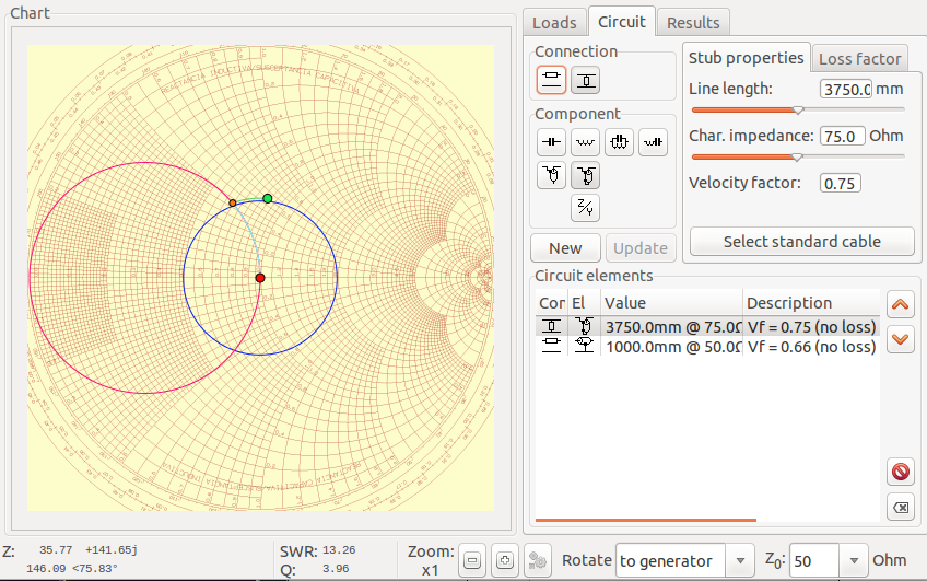
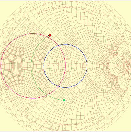
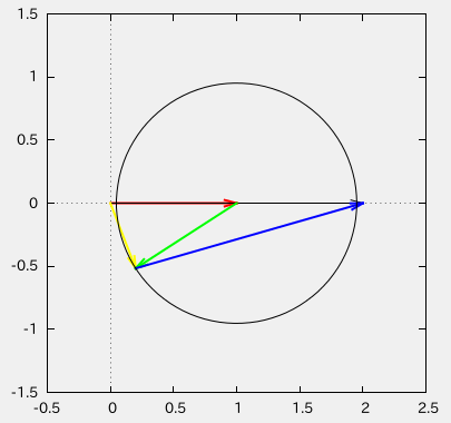
If you remove the dummy load and terminate the cable with an open circuit, the impedance bridge shows:
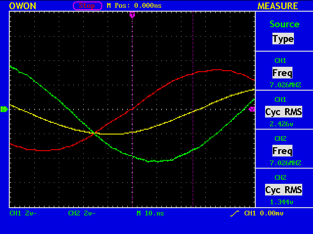
Note: Something is wrong with the green trace. It should be ch1-ch2 signal, but obviously it is not.
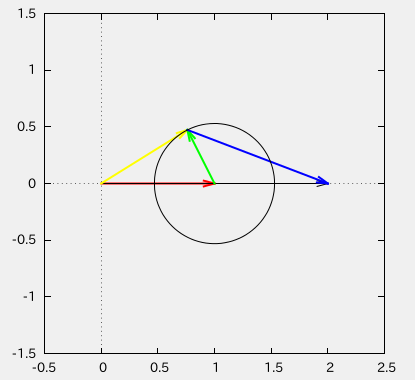
gnuplot> load "gnuplot.txt"
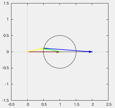
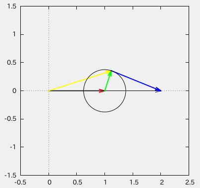
Freq [MHz]=7.026
V1=2.426
V2=1.344
Cursor 1=-2.72e-08
Cursor 2=0.0
vratio=0.553998351195383
phase1 [deg]=-68.798592
phase2 [deg]=0.0
abs(gamma)=0.951950606187447
swr=40.623834169527
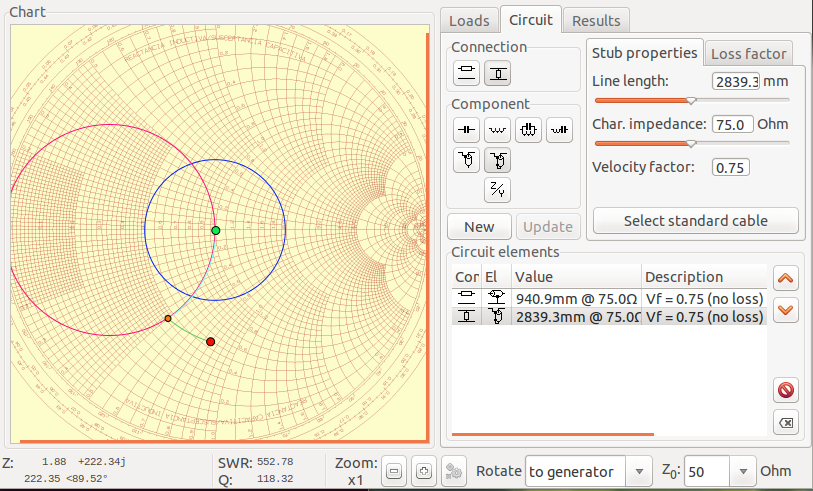
cz={1.33775338471275, -14.7339917147814}
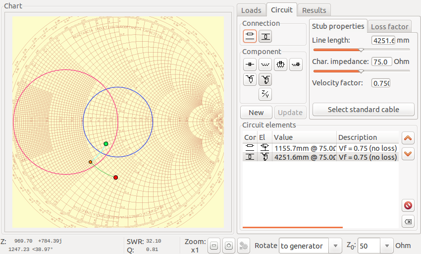
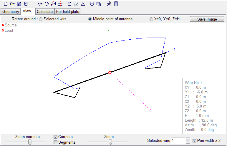
With the cable length of 20m and the velocity factor of 0.67, we have:
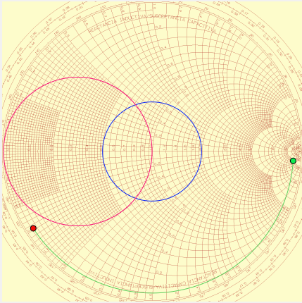
This shows an open circuit at the far end of the cable.