CQ World Wide RTTY Contest

capture_001_28092014_092632

No, I did not participate in the contest, but only listened to (?) some QSOs on the 40m band. Many domestic stations were sending CQs.

I am still not very sure if I will be enjoying this mode of operation someday. Contrary to Morse code, right now the sound does not seem to be very pleasing to my ears.

W1AW/4 NC

was19

It was on the 15m band in the morning local time. The operator was picking up some JA stations on the frequency. I started calling with 50 watts output, and got “OO?” with my first trial. Not bad. It seems that my last letter “D” is often miss copied or simply neglected. My next transmission was with 100 watts, my maximum power, and my callsign repeated twice was copied correctly.

It was OK, but my afterthought is that it could have been more fun if I had insisted on QRP operations.

Wire Antenna and Green Curtain

goya1

One of the advantages of using a wire antenna is that it can be used for multi-purposes, such as for a support for a green curtain.

You can use any climbing plants, but preferably edible ones. My choice this year is bitter melon, or “goya” in Japanese. The fruit, while it is still green, appeared several times on the dinner table and was welcomed with great appreciation.

QRP operation using CW

capture_001_20092014_101840

I usually do not send CQ, but this is just to check if my QRP signals are heard by other stations.

It seems no stations can decode my CQ when the output power is only 2 watts, the minimum power out of my IC-7410. These spots pop up only when the RF power into my diopole is either 5 or 10 watts.

Later I had a QSO on the 40m band with a domestic station 240 miles or 390 km away with the output of 2 watts. The report was 599/599, but it does not give you much information.

If you don't mind

capture_003_17092014_212841

If you don’t mind using two inductors for the L-section network, there is another solution. In this case, the inductor in series is to reach the lower half of the g=1 circle (yellow circle), and therefore its value is somewhat smaller than in the previous case.

capture_002_17092014_212613

Using two inductors instead of an inductor and a capacitor may not be very preferable because of its larger forbidden region and the possible greater power loss.

My First QSO on the 80m band

capture_001_14092014_171924

It was with a domestic station about 400 km or 250 miles north of Tokyo.

dp20

My dipole antenna is for the 40m band with the length of about 10 m for each side, and it does not work well on the 80m band as it is.

capture_002_14092014_102515

Its radiation impedance is ZL=11.8 – 1061 [ohm] and the VSWR value is 1913 at 3.550MHz.

capture_001_14092014_102135

MMANA-GAL is an antenna-analyzing tool, but it can also tell you the network you need in such cases.

If you prefer to solve the problem with a Smith Chart, the following figures may help.

capture_003_14092014_122735a

Since your antenna is short for the band and thus highly capacitive, you first need to add some inductor in series. But its inductance, XL=1082 [ohm], is slightly larger than to exactly compensate the imaginary part of ZL=11.8 – 1061 [ohm] to have XL+ZL not on the Im{Z}=0 line, which is the only straight line on the chart, but on the upper half of the yellow circle.

capture_004_14092014_124305

And then with C2=1613pF in parallel, you will have Zin=50.0 + j0.0 [ohm].

Forbidden Region (4)

ForbiddenUpRight

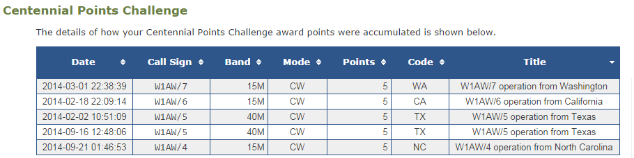
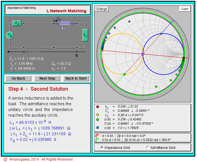
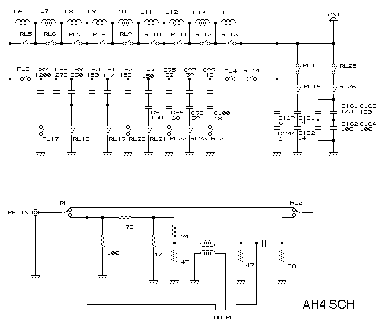
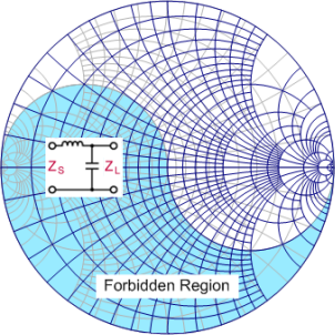
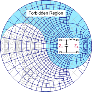
Now let’s take an example to see how there exits a forbidden region for a given type of network.

capture_002_13092014_171949

http://www.amanogawa.com/archive/LMatch/LMatch-2.html

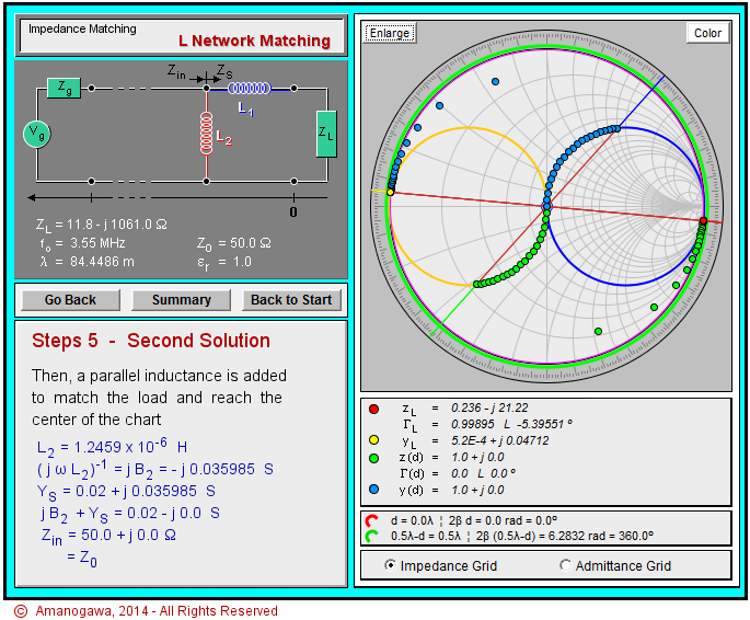
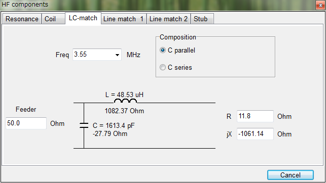
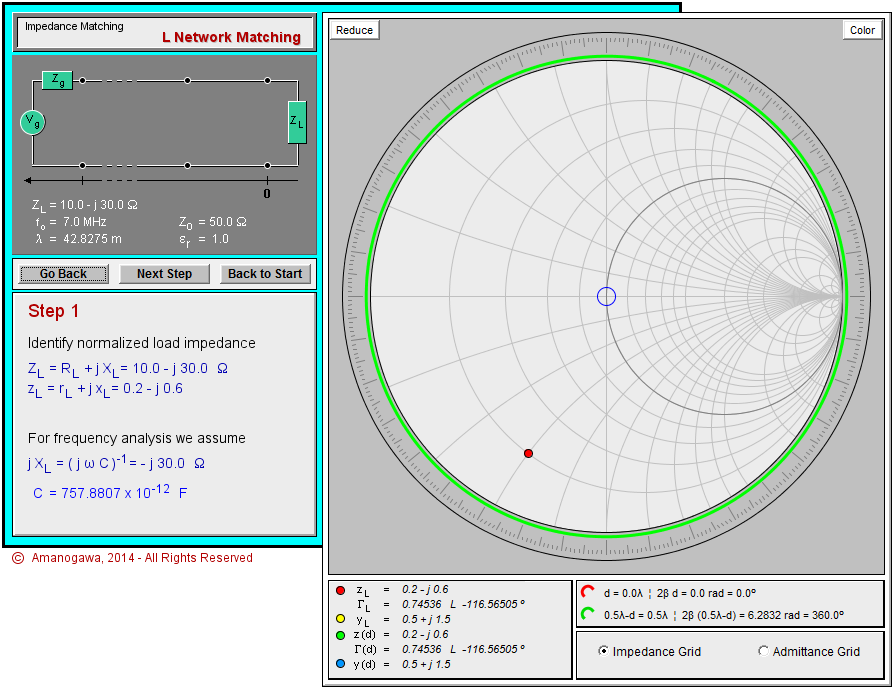
Suppose you antenna has the load impedance of ZL=10.0-j30.0 [ohm] (red dot). Note that ZL does NOT fall onto the forbidden region of the L-section network of the type mentioned in the first figure, so it can somehow be matched to the system impedance of Z0=50 [ohm].

capture_001_13092014_171641

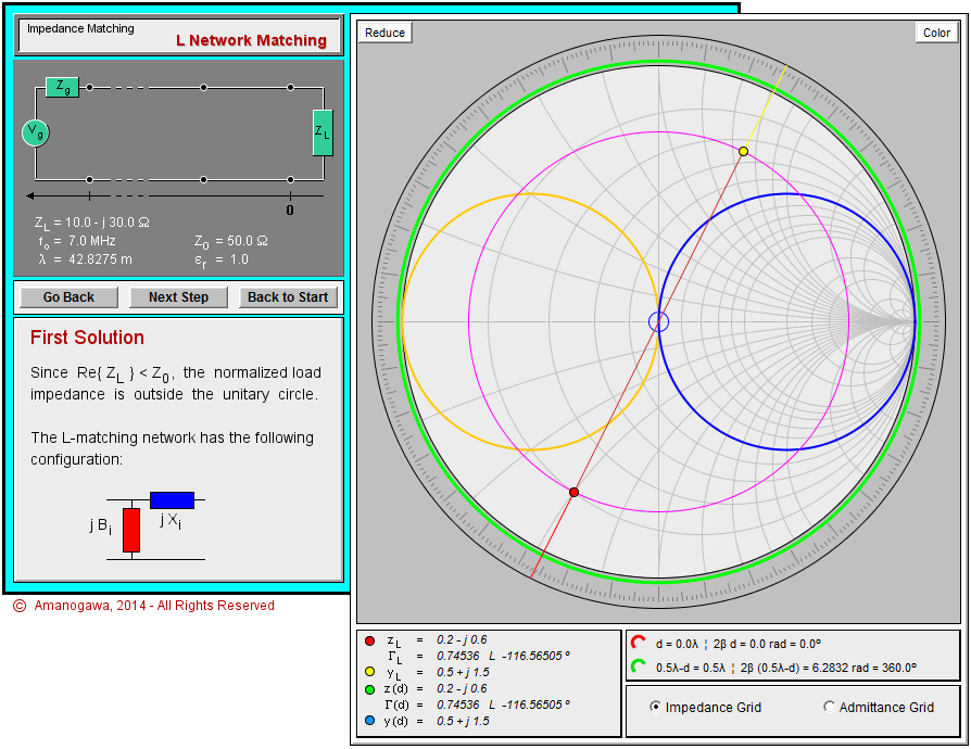
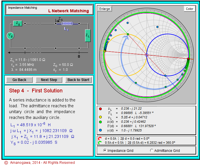
Since you first add some inductance XL (blue box) to ZL in series, and then some capacitance XC (red box) in parallel, the combined XL+ZL must lie on upper half of the constant g=1 circle (yellow circle) on the Smith Chart.

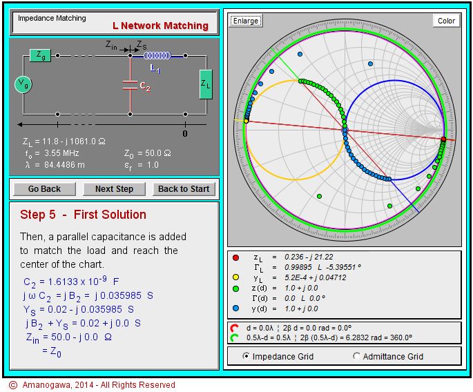
This is because adding a capacitor in parallel means a clockwise movement on a constant g circle, and because your destination is the center of the Smith Chart, namely Z0=50 [ohm]. If you start somewhere from the lower half of the yellow circle, you must use an inductor instead of a capacitor to reach Z0, but this is going to be another story which we are not talking about right now.

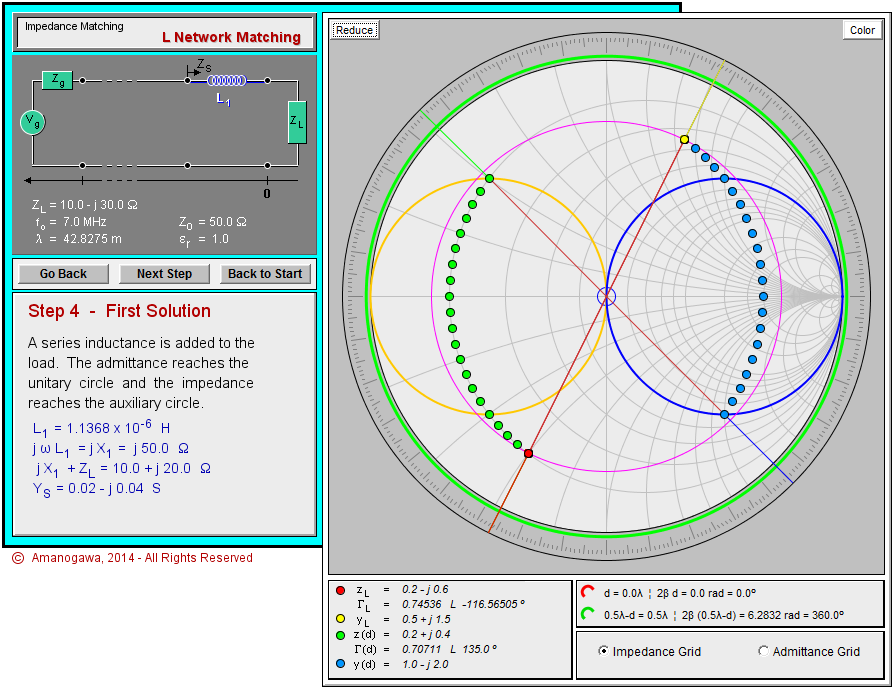
So in summary, XL (blue box) moves your ZL (red dot) onto the place on the upper half of the yellow circle (see the green dots for the locus),

capture_003_13092014_181208

and then you use XC (red box) to finally goes on to Z0. (Never mind the yellow dot and the blue dots. The same things can be said both in terms of impedance (Z) and admittance (Y), where Y=1/Z.)

capture_005_13092014_181448

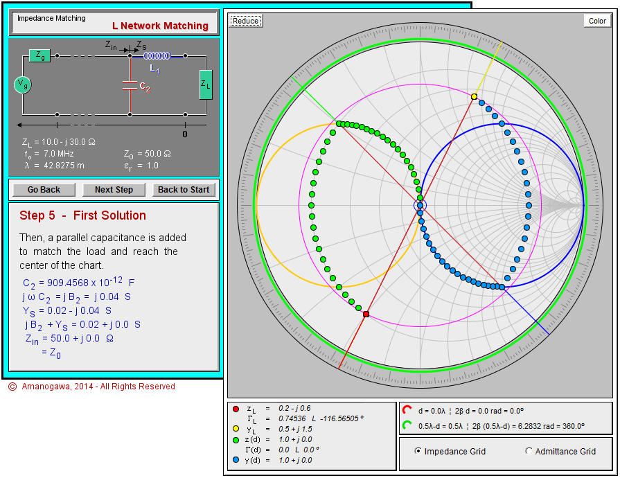
Starting from any ZL (red dot) NOT in the forbidden region, you can always reach Z0 as long as you have an inductor and a capacitor with the appropriate values.

In other words, the forbidden region in this particular type of the network is the area where you can not reach the upper half of the g=1 circle (yellow circle) by adding an inductor in series to ZL (red dot).

Forbidden Region (3)

capture_001_13092014_080227

http://www.icom.co.jp/world/support/download/brochure/pdf/AH-4.pdf

I am using an automatic antenna tuner, ICOM AH-4, for my dipole antenna. Its circuit diagram is not disclosed by ICOM, but JJ2PNX traced the circuit and gives us the following information:

capture_002_13092014_081036

http://www.momose.com/hirofumi/jj2pnx/ah4/index.html

It seems AH-4 can offer two types of L-section networks depending on how the switches RL3 and RL4 (+RL14) are controlled, namely:

ForbiddenUpRight

In the case RL3 is closed, and RL4 being open.

Forbidden LowLeft

In the case RL3 is open, and RL4 being closed.

http://www.rfcafe.com/references/electrical/smith.htm

Forbidden Region (2)

Lsection

http://empc1.ee.ncku.edu.tw/course/RF%20Course%20Note_HR%20Chuang_EE_NCKU/2008-2009/RF_CH05_Impedance_match_HRC_EE_NCKU_2008%201224%20(P21-24%20change).pdf

There are eight types of L-section networks. You often see the types (g) and (h) for antenna tuning units (ATUs).

For each type of the network, a forbidden region is defined. Some examples are:

Forbidden

Ibid.

Since the impedance, ZL=R+jX, of your antenna could be anything, or anywhere on the Smith Chart, you must select the appropriate types of the network depending on the antenna you are using, or on the band you are operating, so that the impedance ZL does not fall onto the forbidden region.

Note that if you only have two types, such as (a) and (d) in the above figure, or (h) and (g) in the previous figure, you can cover all the cases assuming the values of the inductance and the capacitance can be arbitrarily large or small.