/proc/asound/card?/stream?

alsa

I do not know (and forget) many things.

% arecord -l
**** List of CAPTURE Hardware Devices ****
card 0: MID [HDA Intel MID], device 0: ALC889 Analog [ALC889 Analog]
  Subdevices: 1/1
  Subdevice #0: subdevice #0
card 0: MID [HDA Intel MID], device 2: ALC889 Alt Analog [ALC889 Alt Analog]
  Subdevices: 2/2
  Subdevice #0: subdevice #0
  Subdevice #1: subdevice #1
card 2: CODEC [USB Audio CODEC], device 0: USB Audio [USB Audio]
  Subdevices: 1/1
  Subdevice #0: subdevice #0

O.K. Now my device (IC-7410) is hw:2,0. (It depends on the sequence you power on your devices.)

% sprigmm /dev/ttyUSB1 hw:2,0 16000 1 hw:0,0 48000 2 <- note the bitrate

Run my program with the bitrate of hw:2,0 to be 16000bps.

% cat /proc/asound/card2/stream0
Burr-Brown from TI USB Audio CODEC at usb-0000:00:1a.0-1.3.1, full speed : USB Audio

Playback:
  Status: Stop
  Interface 1
    Altset 1
    Format: S16_LE
    Channels: 2
    Endpoint: 2 OUT (ADAPTIVE)
    Rates: 32000, 44100, 48000
  Interface 1
    Altset 2
    Format: S16_LE
    Channels: 1
    Endpoint: 2 OUT (ADAPTIVE)
    Rates: 32000, 44100, 48000
  Interface 1
    Altset 3
    Format: S8
    Channels: 2
    Endpoint: 2 OUT (ADAPTIVE)
    Rates: 32000, 44100, 48000
  Interface 1
    Altset 4
    Format: S8
    Channels: 1
    Endpoint: 2 OUT (ADAPTIVE)
    Rates: 32000, 44100, 48000
  Interface 1
    Altset 5
    Format: U8
    Channels: 2
    Endpoint: 2 OUT (ADAPTIVE)
    Rates: 32000, 44100, 48000
  Interface 1
    Altset 6
    Format: U8
    Channels: 1
    Endpoint: 2 OUT (ADAPTIVE)
    Rates: 32000, 44100, 48000

Capture:
  Status: Running <- ### this is it! ###
    Interface = 2
    Altset = 10
    Packet Size = 34
    Momentary freq = 16000 Hz (0x10.0000)
  Interface 2
    Altset 1
    Format: S16_LE
    Channels: 2
    Endpoint: 4 IN (ASYNC)
    Rates: 48000
  Interface 2
    Altset 2
    Format: S16_LE
    Channels: 1
    Endpoint: 4 IN (ASYNC)
    Rates: 48000
  Interface 2
    Altset 3
    Format: S16_LE
    Channels: 2
    Endpoint: 4 IN (ASYNC)
    Rates: 44100
  Interface 2
    Altset 4
    Format: S16_LE
    Channels: 1
    Endpoint: 4 IN (ASYNC)
    Rates: 44100
  Interface 2
    Altset 5
    Format: S16_LE
    Channels: 2
    Endpoint: 4 IN (ASYNC)
    Rates: 32000
  Interface 2
    Altset 6
    Format: S16_LE
    Channels: 1
    Endpoint: 4 IN (ASYNC)
    Rates: 32000
  Interface 2
    Altset 7
    Format: S16_LE
    Channels: 2
    Endpoint: 4 IN (ASYNC)
    Rates: 22050
  Interface 2
    Altset 8
    Format: S16_LE
    Channels: 1
    Endpoint: 4 IN (ASYNC)
    Rates: 22050
  Interface 2
    Altset 9
    Format: S16_LE
    Channels: 2
    Endpoint: 4 IN (ASYNC)
    Rates: 16000
  Interface 2
    Altset 10
    Format: S16_LE
    Channels: 1
    Endpoint: 4 IN (ASYNC)
    Rates: 16000
  Interface 2
    Altset 11
    Format: S8
    Channels: 2
    Endpoint: 4 IN (ASYNC)
    Rates: 16000
  Interface 2
    Altset 12
    Format: S8
    Channels: 1
    Endpoint: 4 IN (ASYNC)
    Rates: 16000
  Interface 2
    Altset 13
    Format: S8
    Channels: 2
    Endpoint: 4 IN (ASYNC)
    Rates: 8000
  Interface 2
    Altset 14
    Format: S8
    Channels: 1
    Endpoint: 4 IN (ASYNC)
    Rates: 8000
  Interface 2
    Altset 15
    Format: S16_LE
    Channels: 2
    Endpoint: 4 IN (SYNC)
    Rates: 11025
  Interface 2
    Altset 16
    Format: S16_LE
    Channels: 1
    Endpoint: 4 IN (SYNC)
    Rates: 11025
  Interface 2
    Altset 17
    Format: S8
    Channels: 2
    Endpoint: 4 IN (SYNC)
    Rates: 11025
  Interface 2
    Altset 18
    Format: S8
    Channels: 1
    Endpoint: 4 IN (SYNC)
    Rates: 11025

http://alsa.opensrc.org/Proc_asound_documentation

See the first several lines after the “Capture:” line.

Antenna Switch

Soft66antsw

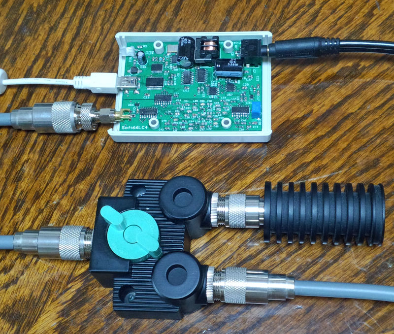
Here is a manual antenna switch for Soft66LC4. The RF input port of the device is connected either to a main antenna or to a dummy load to be grounded.

The main antenna is also connected to IC-7410 all the time, so you must remember to change the switch position before transmitting.

One problem is that the LO of Soft66LC4 is always audible indepedent of the switch position.

waterfall4

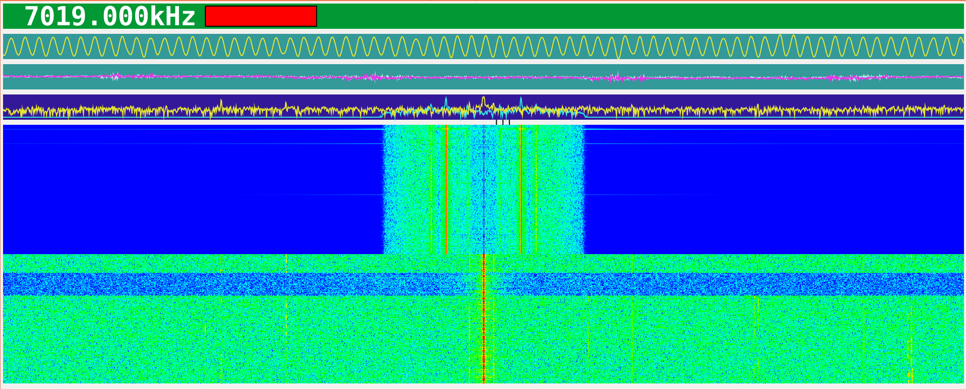
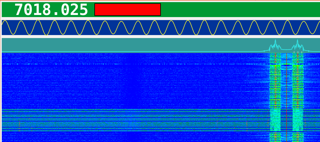
A 1kHz tone from Soft66LC4 with its LO at 7020kHz is visible at the upper half of the waterfall showing the audio signal from IC-7410. The switch is momentarily changed to the ground position, the period of which you can observe at the lower half of the waterfall, but the strength of the tone does not change regardless of the switch position.

IC-7410 Rig Control Program and Soft66LC4 (9)

waterfall3

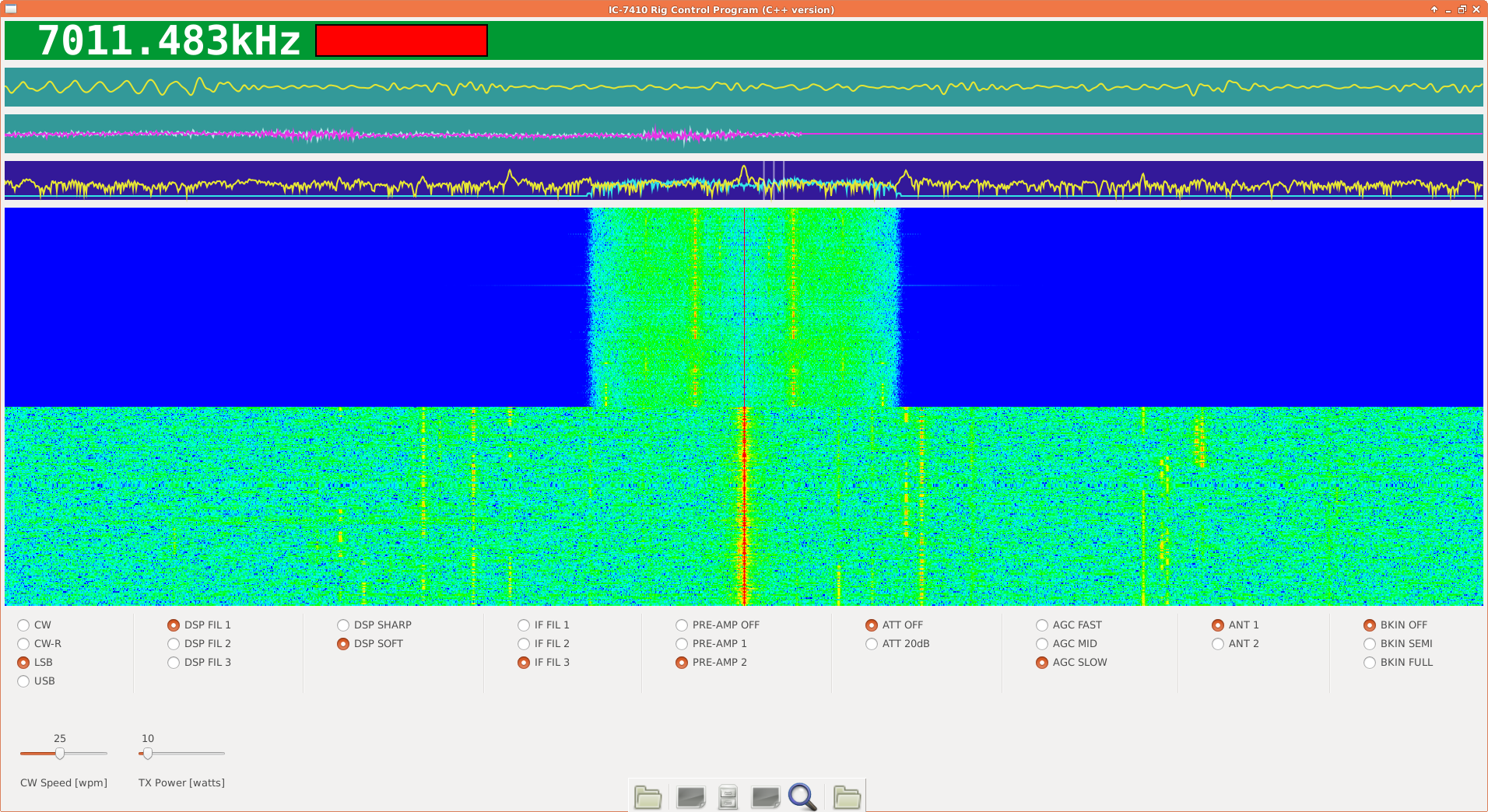
The RF signal from the receiving antenna is fed into both IC-7410 (the upper half of the waterfall) and Soft66LC4 (the lower half).

Never never transmit in this configuration!

The DC is at the center of the waterfall, but its actual frequency is 7011.483kHz (+600Hz) for IC-7410, and 7020.000kHz for Soft66LC4, the latter frequency not being controlled from the program right now. Also the frequency span for the waterfall differs for the two signals.

git checkout HEAD^1

github1

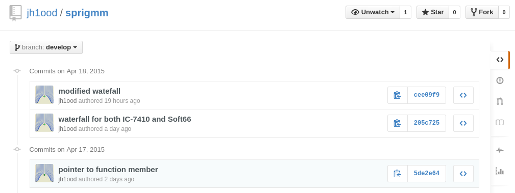
I always do % git push only if the code runs (almost) successfully, and I pushed twice yesterday. I found today that my latest code does not run properly any more. What happened?

I went back a single step to my previous commit, and then two, where I found the one, pointer to function member, that seems to be OK.

github2

Where did I go wrong?

IC-7410 Rig Control Program and Soft66LC4 (8)

waterfall2

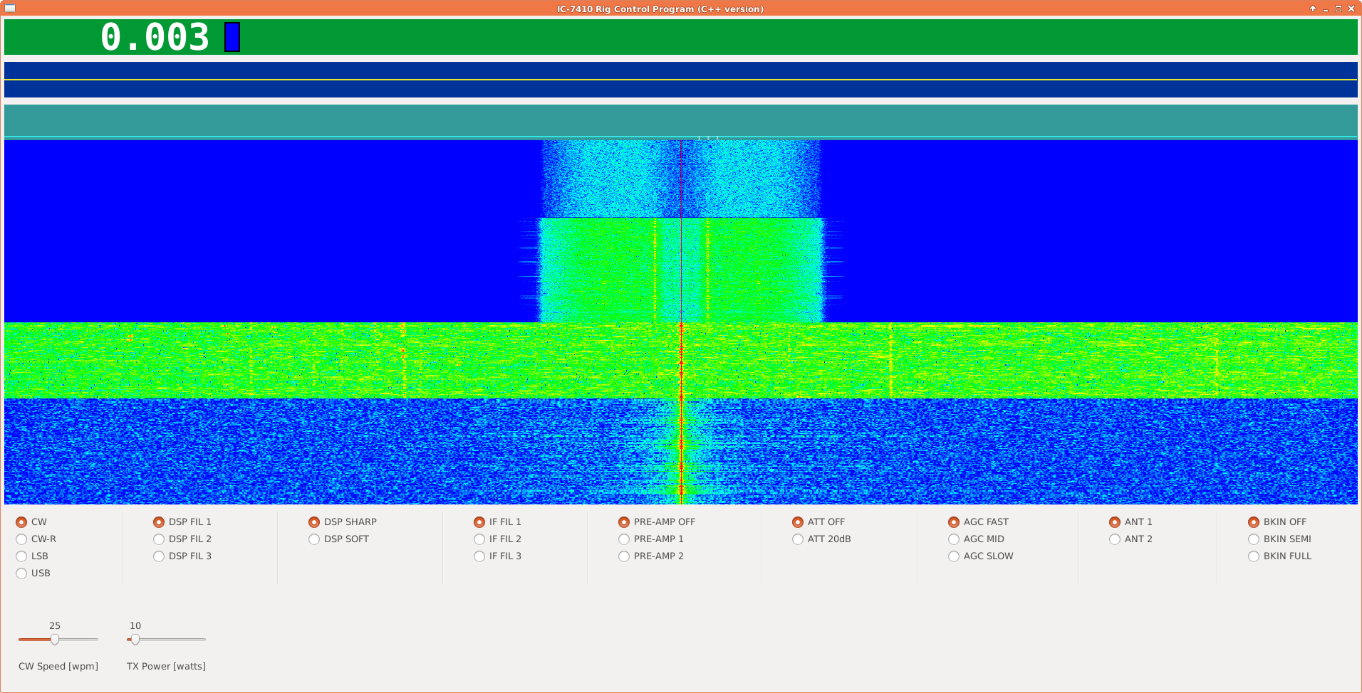
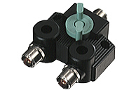
Now the upper half of the waterfall is for the signal from IC-7410, and the lower half from Soft66LC4. The bandwidth is much wider for the latter. Currently, the RF signal from the receiving antenna is switched between the two devices using a coax switch, CX210A, so I need a splitter to enable simultaneous receiving.

cx210a

Pointers to Function Members (2)

waterfall

This waterfall display looks weird, but it is because the sound signals from two devices, IC-7410 and Soft66LC4, are interleaved almost line by line. A narrow band signal is from IC-7410, and a broad band from Soft66LC4.

I need to change the whole structure of the program to have two waterfall windows instead of interleaved lines, but it seems the following code works as far as the callback function for alsa audio system is concerned.

Sound *mysound1;
Sound *mysound2;

int main(int argc, char *argv[])
{
    if (argc == 5) {
    	mysound1 = new Sound{argv[2], argv[3], argv[4]};
    } else if (argc == 8) {
        mysound1 = new Sound{argv[2], argv[3], argv[4]};
        mysound2 = new Sound{argv[5], argv[6], argv[7]};
    } else {
	cout << "Usage (IC-7410 only)      : " << argv[0] <<
	    " /dev/ttyUSB0 hw:2,0 32000 1 \n";
	cout << "Usage (IC-7410 and Soft66): " << argv[0] <<
	    " /dev/ttyUSB0 hw:2,0 32000 1 hw:0,0 48000 2 \n";
	return false;
    }
class Sound {
  public:
    Sound(char *, const char *, const char *);
    int asound_set_hwparams(snd_pcm_t * handle, snd_pcm_hw_params_t * hwparams);
    int asound_set_swparams(snd_pcm_t * handle, snd_pcm_sw_params_t * swparams);
    void asound_async_callback(snd_async_handler_t * ahandler);

    snd_pcm_sframes_t buffer_size;
    snd_pcm_sframes_t period_size;
    snd_pcm_t *handle;
    snd_pcm_hw_params_t *hwparams;
    snd_pcm_sw_params_t *swparams;
    snd_async_handler_t *ahandler;
extern Sound *mysound1;
extern Sound *mysound2;

void asound_callback1_wrapper(snd_async_handler_t * ahandler)
{
    mysound1->asound_async_callback(ahandler);
}

void asound_callback2_wrapper(snd_async_handler_t * ahandler)
{
    mysound2->asound_async_callback(ahandler);
}
Sound::Sound(char *s, const char *r, const char *c)
{
    sound_device = s;
    rate = atoi(r);
    channels = atoi(c);

    snd_pcm_hw_params_alloca(&hwparams);
    snd_pcm_sw_params_alloca(&swparams);

    if (0) {
    } else if (channels == 1) {
    	err = snd_async_add_pcm_handler(&ahandler, handle, asound_callback1_wrapper, samples);	/* callback */
    } else if (channels == 2) {
    	err = snd_async_add_pcm_handler(&ahandler, handle, asound_callback2_wrapper, samples);	/* callback */
    }

https://github.com/jh1ood/sprigmm/tree/develop

Pointers to Function Members

How do I pass a pointer-to-member-function to a signal handler, X event callback, system call that starts a thread/task, etc?

I did not know it is an FAQ, and wasted many hours trying this way and that.

The_C++_Programming_Language,_Fourth_Edition

In the book, the topic appears around here:

pointers

    if (argc == 5) {
        Sound ic7410 {argv[2], argv[3], argv[4]};
    } else if (argc == 8) {
        Sound ic7410 {argv[2], argv[3], argv[4]};
        Sound soft66 {argv[5], argv[6], argv[7]};
    } else {
    	cout << "Usage (IC-7410 only)      : " << argv[0] << " /dev/ttyUSB0 hw:2,0 32000 1 \n";
    	cout << "Usage (IC-7410 and Soft66): " << argv[0] << " /dev/ttyUSB0 hw:2,0 32000 1 hw:0,0 48000 2 \n";
    	return false;
    }

We have two audio devices, ic7410 and soft66, and each requires its callback function.

class Sound {
public:
	Sound(char*, const char*, const char*);
//	void asound_async_callback(snd_async_handler_t * ahandler); /* fix it */
private:
	int  asound_set_hwparams(snd_pcm_t * handle, snd_pcm_hw_params_t * hwparams);
	int  asound_set_swparams(snd_pcm_t * handle, snd_pcm_sw_params_t * swparams);
	snd_pcm_hw_params_t *hwparams;
	snd_pcm_sw_params_t *swparams;
}

IC-7410 Rig Control Program and Soft66LC4 (7)

soft66waterfall4

This waterfall is with the following code.

    if(channels == 2) { /* for my Soft66LC4 only */
      for(int i =0; i < NFFT; i+=2) {
 		  double i1 = samples[i  ] + (-246.618); /* DC offset */
    	  double q1 = samples[i+1] + (-222.262);
    	  double i2 = i1;
    	  double q2 = -0.32258 * i1 + 1.1443 * q1; /* gain and phase correction */
    	  double i3 = q2; /* swap IQ */
    	  double q3 = i2;
    	  audio_signal[i]   = i3;
    	  audio_signal[i+1] = q3;
      }
    }

Note that IQ signals are swapped now, so the signals higher than the LO, which is in this case 7020kHz, appear on the right half of the display.

IC-7410 Rig Control Program and Soft66LC4 (6)

IQraw

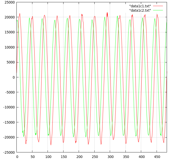
Here is a raw IQ data plot for 12 cycles, which contain 484 samples. We are going to obtain parameters to correct the gain and the phase errors. First, the DC offset.

% awk 'BEGIN {n=484} {a=a+$1; b=b+$2} END {print a/n,b/n}' data1c.txt
-246.618 -222.262

We assume, after correcting the DC offset, that I’=A*cos(wt) and Q’=B*sin(wt+C). Then we have (I’,Q’)=([A,0],[B*sin(C)+B*cos(C)]) (cos(wt),sin(wt)). By inverting the 2×2 matrix, we have (I,Q)=([B*cos(C),0],[-B*sin(C),A]) (I’,Q’), where I and Q are ideal (and normalized) IQ signals, namely cos(wt) and sin(wt).

Noting that /I’I’/=(1/2)*A^2, /Q’Q’/=(1/2)*B^2, and /I’Q’/=(1/2)*A*B*sin(C), we have A=sqrt(2*/I’I’/), B=sqrt(2*/Q’Q’/), and sin(C)=(2/(A*B))*/I’Q’/, where /*/ is defined to be the average over the period.

% awk 'BEGIN {n=484;d1=-246.618;d2=-222.262} {a=a+($1-d1)*($1-d1); b=b+($2-d2)*($2-d2)} END {print a/n,b/n}' data1c.txt
2.24414e+08 1.89215e+08

Therefore, /I’I’/=2.24414e+08, and /Q’Q’/=1.89215e+08, which means A=21185.6, and B=19453.3.

% awk 'BEGIN {n=484;d1=-246.618;d2=-222.262} {a=a+($1-d1)*($2-d2)} END {print a/n}' data1c.txt
6.3263e+07

Next, /I’Q’/=6.3263e+07, which means sin(C)=0.30701, or C=0.31204[rad]=17.879[deg].

And finally, we get B*cos(C)=18513.86, and -B*sin(C)=-5972.26.

If we multiply a constant, 1/B*cos(C), to the matrix ([B*cos(C),0],[-B*sin(C),A]) so that I’ becomes immediately I, as we assumed in our previous articles, we have:

(I,Q)=([1,0],[-tan(C),A/(B*cos(C))]) (I’,Q’)=([1,0],[-0.32258,1.1443]) (I’,Q’)

My first guess by observations was that “C1 to be -0.32 and C2 to be 1.14”, and it proves that I guess very exactly!

IC-7410 Rig Control Program and Soft66LC4 (5)

soft66waterfall3

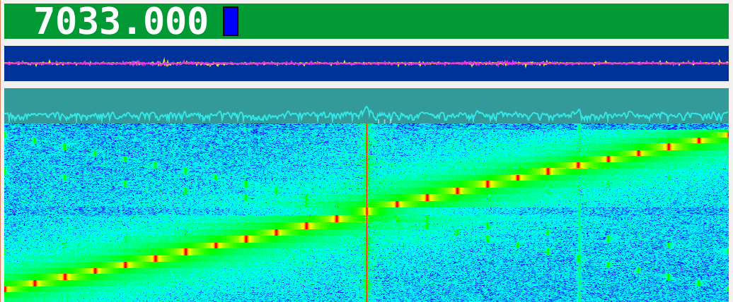
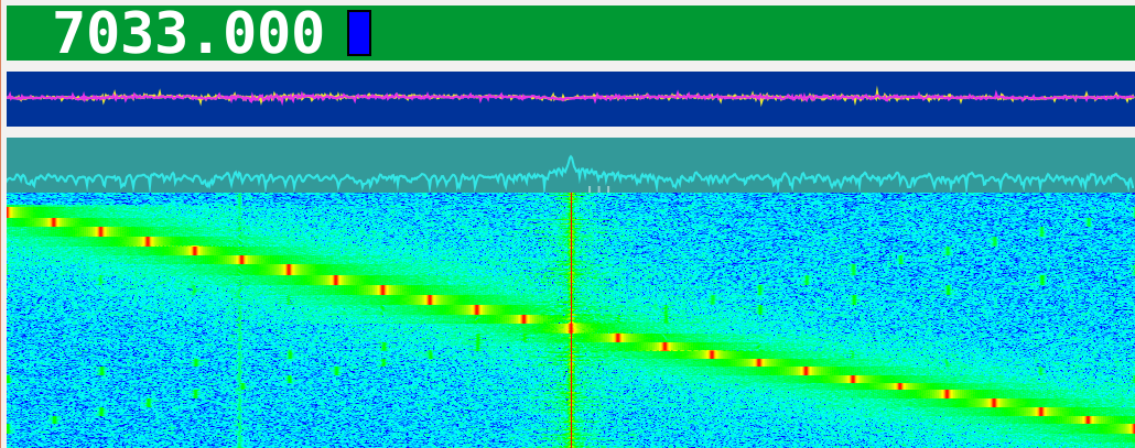
Let’s see now if the following simple adjustment is effective with the frequencies other than LO+600Hz.

if(channels == 2) {
  for(int i =0; i < NFFT; i+=2) {
      audio_signal[i]   = samples[i] + 400.0;
      audio_signal[i+1] = -0.32*samples[i] + 1.14*samples[i+1];
  }
}

The RF frequency is varied with 1kHz step, and the center is at 7020kHz. You can observe the images as faint green dots on the waterfall, but on the whole it looks reasonably fine, doesn’t it?

You can see the waterfall without the adjustment in my previous article.