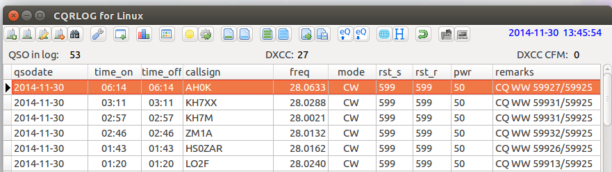
I have been using Logger32 on Windows, but since I want to avoid using Microsoft Windows wherever possible, I started to try CQRLOG.
A notebook and a pencil might be a better choice for QRS and QRP operations.

Ham Radio Blog
I have been using Logger32 on Windows, but since I want to avoid using Microsoft Windows wherever possible, I started to try CQRLOG.
A notebook and a pencil might be a better choice for QRS and QRP operations.
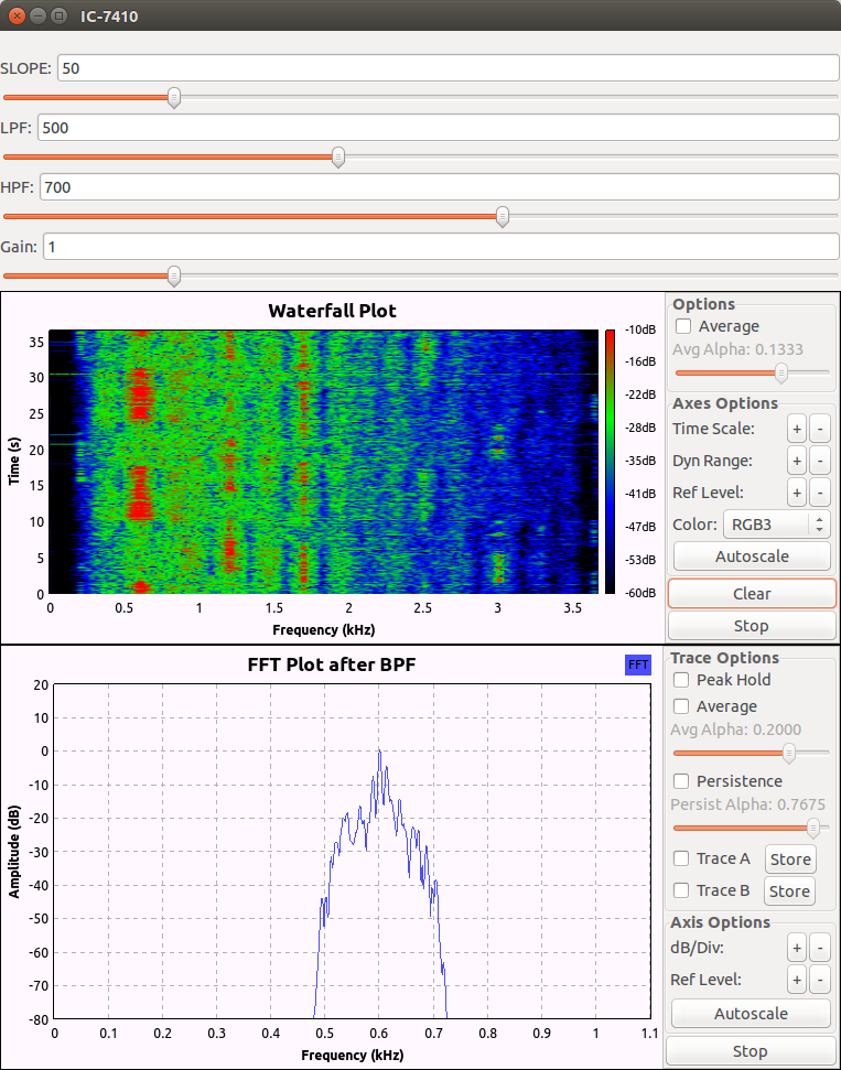
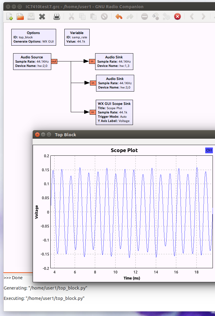
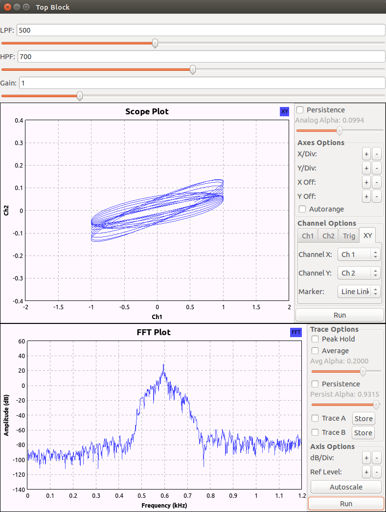
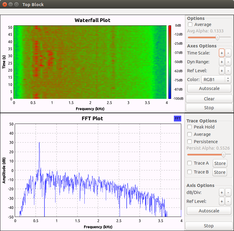
I suppose this is a workable solution which has some practical values. The upper plot is a mini band scope, and the lower plot is an aid for CW tuning. The audio output is band-pass filtered with the parameters adjustable by the sliders before being sent to the USB audio output device, Zoom G3.
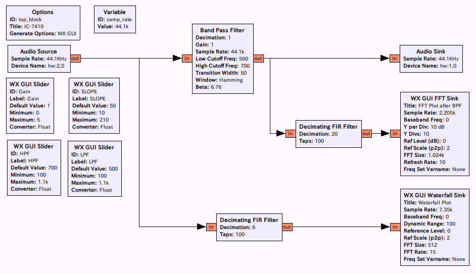
Note that the card and the device numbers may change, and now Zoom G3 is hw:1,0.
user1@UNIX [03:39:45] [~/Music]
% aplay -l
**** List of PLAYBACK Hardware Devices ****
card 0: MID [HDA Intel MID], device 0: ALC889 Analog [ALC889 Analog]
  Subdevices: 1/1
  Subdevice #0: subdevice #0
card 0: MID [HDA Intel MID], device 3: ALC889 Digital [ALC889 Digital]
  Subdevices: 1/1
  Subdevice #0: subdevice #0
card 1: Series [ZOOM G Series], device 0: USB Audio [USB Audio]
  Subdevices: 0/1
  Subdevice #0: subdevice #0
card 2: CODEC [USB Audio CODEC], device 0: USB Audio [USB Audio]
  Subdevices: 1/1
  Subdevice #0: subdevice #0
card 3: HDMI [HDA ATI HDMI], device 3: HDMI 0 [HDMI 0]
  Subdevices: 1/1
  Subdevice #0: subdevice #0
The Linux sound system is rather complicated partly due to historical reasons. It depends on how you construct you system, or which distribution you use. For example, if you wish to use a Firewire (IEEE 1394) sound device, the minimum requirement is: lilbraw1394, llibffado, libsndfile, jackd, and your application program, which you can write in one hundred lines or so in C.
Assuming you have installed ALSA in your system, you can find your sound devices and play sound as in the following manner:
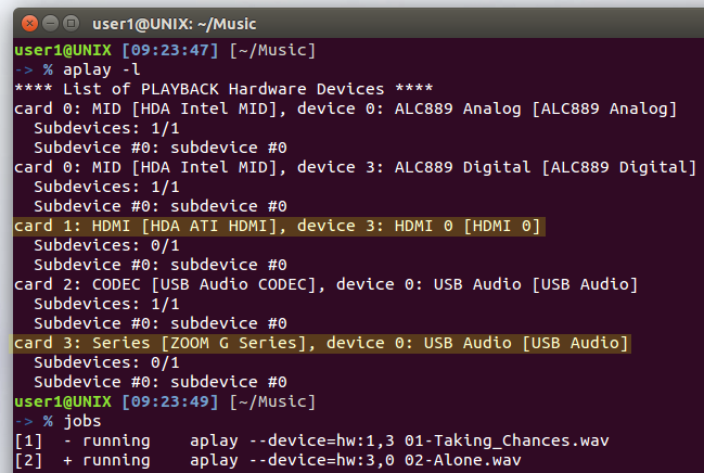
Card 0 is the device on the motherboard, Card 1 is on the display with HDMI sound capability, Card 2 and Card 3 are USB sound devices on IC-7410 and Zoom G3, respectively. Two songs are played simultaneously using two different devices, namely Card 1 and Card 3.
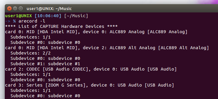
This is a list of input devices. Card 1 does not appear here because it is an output only device.
user1@UNIX [10:36:01] [~/Music]
% arecord -f cd --device=hw:2,0 IC7410.wav
Recording WAVE 'IC7410.wav' : Signed 16 bit Little Endian, Rate 44100 Hz, Stereo
user1@UNIX [10:37:18] [~/Music]
% aplay --device=hw:3,0 IC7410.wav
Playing WAVE 'IC7410.wav' : Signed 16 bit Little Endian, Rate 44100 Hz, Stereo
Record a sound from IC-7410 and play on Zoom G3, both via USB I/F.
user1@UNIX [10:38:21] [~/Music]
% alsaloop --cdevice hw:2,0 --pdevice hw:3,0
This is a loopback between two devices.
In this configuration the sound from IC-7410 is distributed to both the display and Zoom G3.
A very simple method is to draw a Lissajous curve against a reference signal of 600Hz.
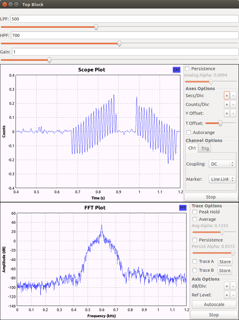
Another way is to demodulate the received audio signal with a 600Hz carrier, assuming you have set the CW pitch to be 600 Hz.
Note that in the scope plot the 1200 Hz component looks like a 80 Hz signal due to undersampling of the scope.
If a low-pass filter is employed to eliminate the 1200 Hz component, and if a perfect tuning is attained, you will observe a square wave corresponding to a dot or a dash. It seems the morse code was two dashes or the letter M.
You will also see that the half period of the filtered signal is around 0.3 sec, so the beat frequency is about 1.7 Hz. Unfortunately, you can not tell whether you should tune up or tune down from the figure. You need to do more sophisticated signal processing dealing with complex numbers, or analytic signals.
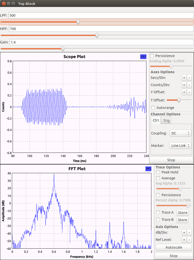
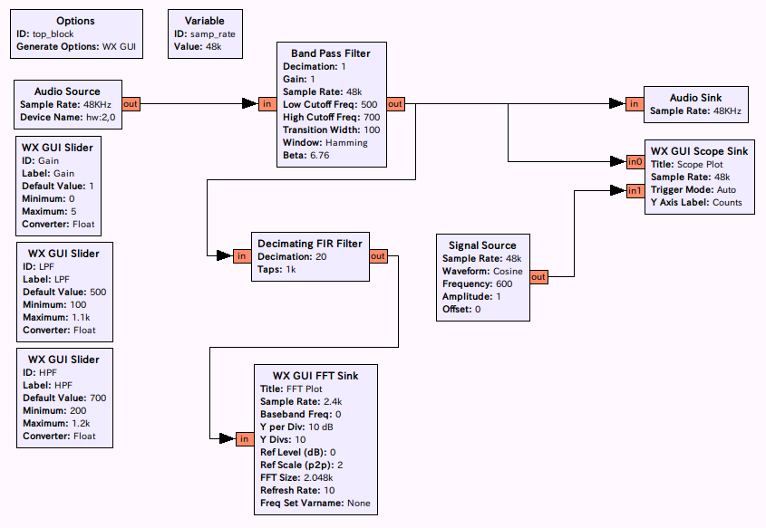
Added a band pass filter for audio output from the PC. The sound from the rig can be muted.
For band scope like operations, I usually watch with my widest filter (3.6kHz bandwidth) of the rig, so my minimum requirement is a modest band pass filter and something like a CW tuning indicator.
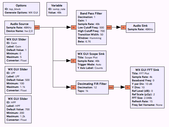
Three GUI sliders are used to change the filter characteristics in real time.
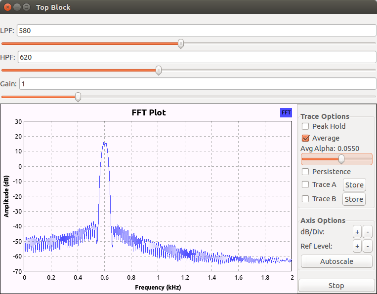
This figure shows a typical BPF chareacteristics, and is obtained with a built-in Gaussian Noise Source.
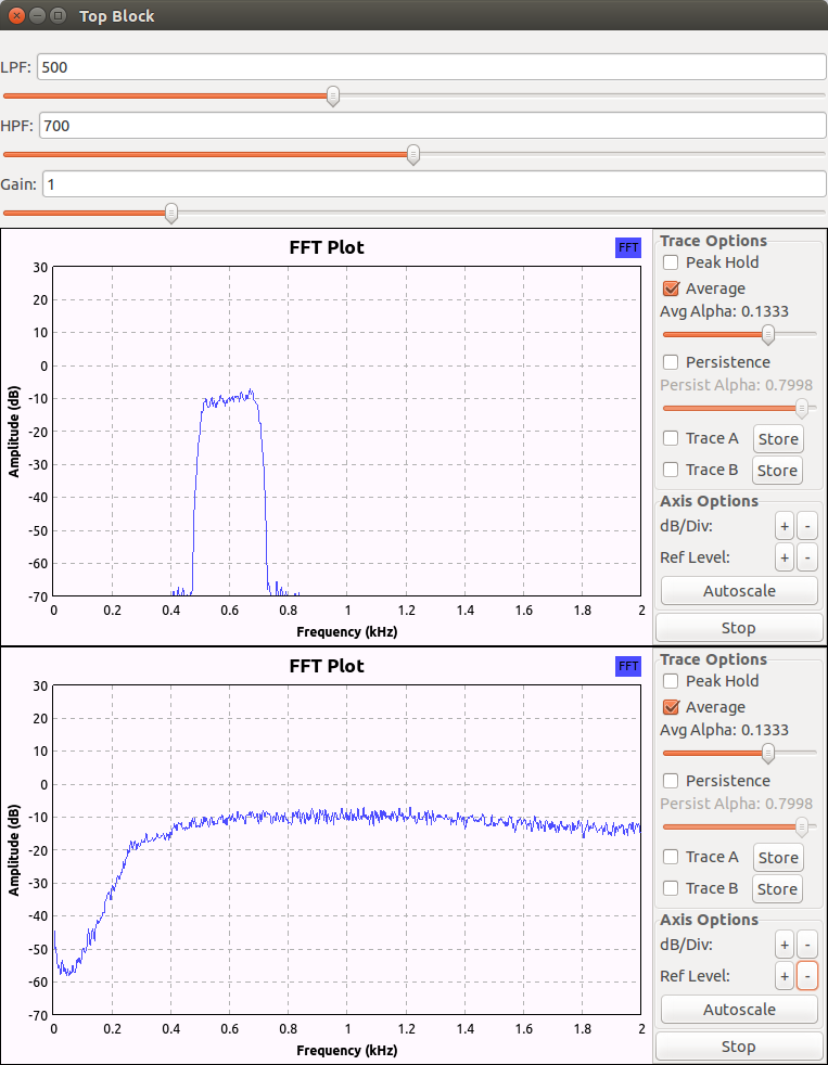
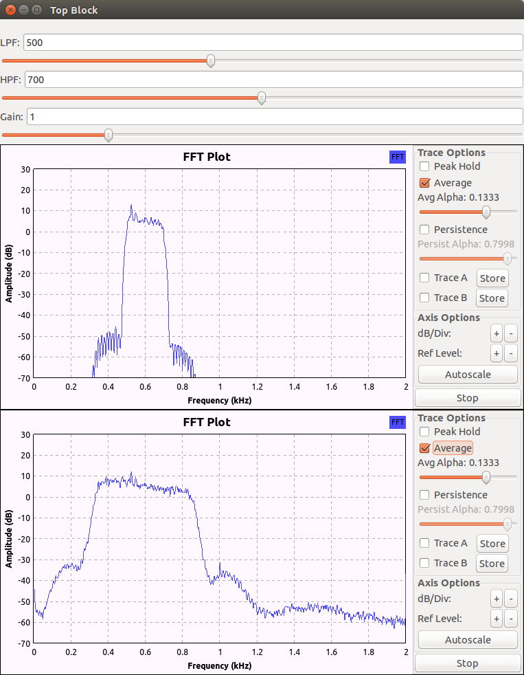
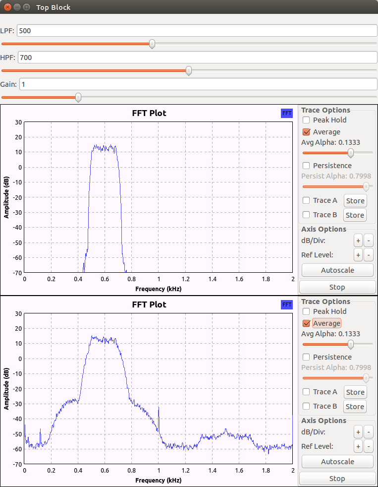
In these three figures the sound from the rig, when there was no significant signals on the air, is used as a noise source. The DSP filter bandwidth was 3.6kHz, 500Hz and 250Hz, respectively. The first plot is after filtering, and the second plot is before filtering in each figure.
GNU Radio revisited.
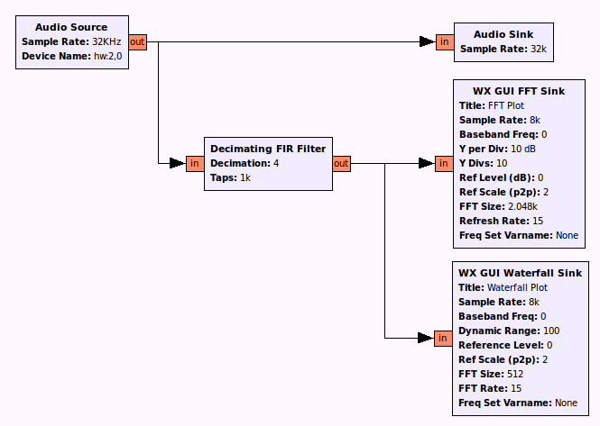
The signal flow is the same as before except for the decimation filter. I am not sure if I need any audio signal processing here for my ears.
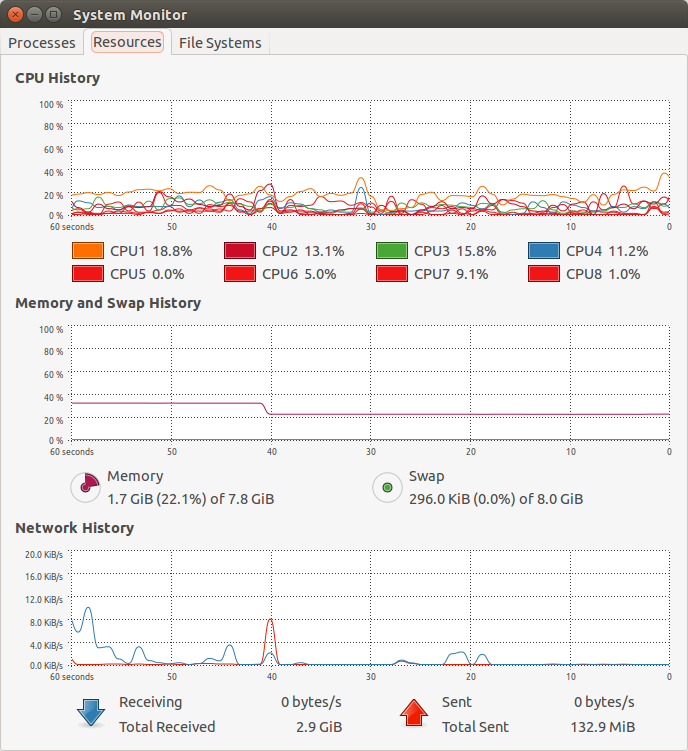
A shallow dip in memory history is due to closing a web browser.
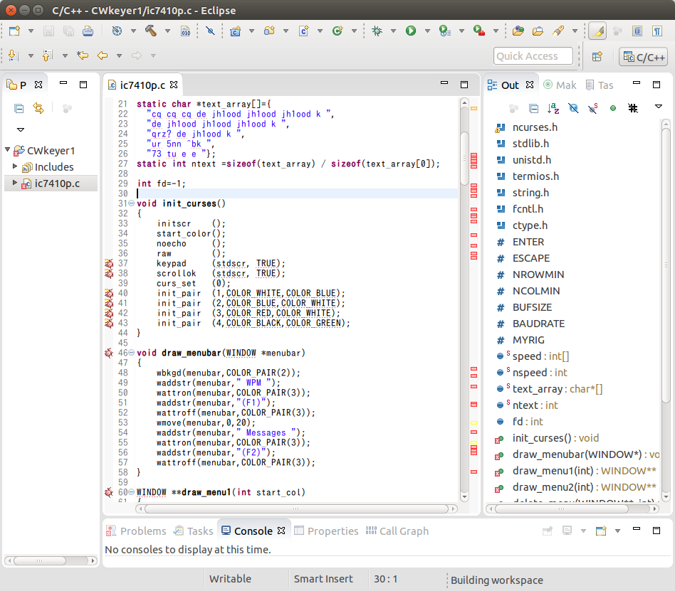
I use Eclipse only on and off, and I can not remember which version it was last time. Anyway it is Luna now.
We have lots of errors because Ncurses is not yet installed on the machine.
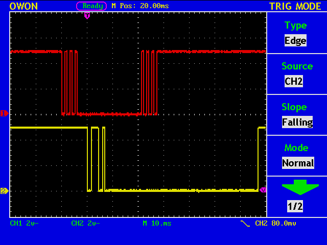
This figure shows a pattern generator output (red), and an actual signal from the paddle (yellow). Not bad?
Two signals are not linked, so observing two traces at the same time is just a coincidence. And I must add that I do not have key chattering every time I manipulate the paddle. Some patience was required to get this nice picture.
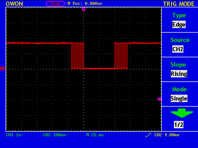
This is a test pattern generated by an Arduino board to simulate the manipulation of a paddle and the key chattering.
The signal will be fed into another Arduino board, on which I will test my CW Keyer program.
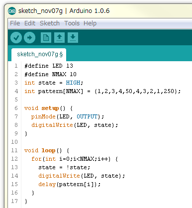
Any program will do, and this is only an example.
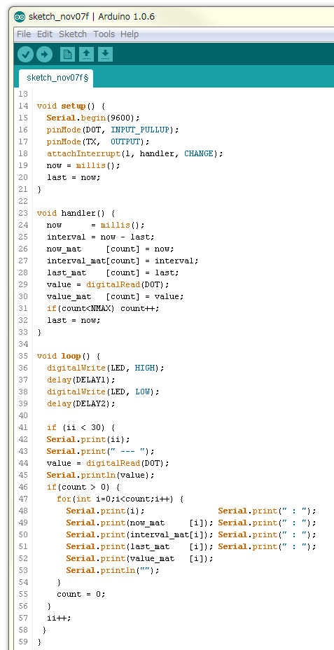
In real life, we always have key chattering, so we must take care of it. This is a short program to see what happens when we manipulate a paddle.
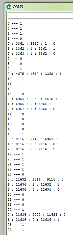
Each short line shows the key up(1)/down(0) every 500 mS. The longer lines show how many times an interrupt occurs for each manipulation, namely key up or key down. It seems that a single digitalRead() immediately after an interrupt is not very reliable.
Also note that the number of interrupts per manipulation is not always an odd number. See the last five lines. Theoretically the number must be odd because there IS a status change.