Awk Tips (3)

IC7410internal0

Now, it seems OK. The side-tone frequency is 500Hz.

IC7410internal1

The phase difference with the delay of four samples is almost exactly 90 degrees. The dots in the circle is due to the rise and fall transients of the envelope.

The message, CQ CQ CQ de…, is generated internally in IC-7410 using its one of four memories. So the dot-to-dash ratio, etc., should be nearly perfect.

Awk Tips (2)

capture_001_27042014_082130

Oops, the envelope (green) is far from the constant.

capture_002_27042014_082245

This is an x-y plot of the side tone and its delayed version. The delay is four sample intervals, which should relate to 90 degrees phase difference with the sampling frequency of 8kHz. Oh, yes! I forgot to set the side-tone frequency to 500Hz, or more exactly, I set the frequency all right through the computer I/F, but when I touch one of the control knobs on my rig, say the AF volume, the rig automatically read the setting of other volumes, and the side-tone frequency becomes 600Hz, which is my preferred tone.

Awk Tips

capture_002_20042014_163805

An AWK one liner program to normalize the signal.

% gawk 'NR==FNR{if($0>max) max=$0;next} {$0=$0/max}1' file1 file1 > file2

The program is not very efficient, because every line is checked to determine if the file is read for the first time.

capture_001_20042014_163731

But, it works.

My Keying (7)

capture_001_16042014_124826

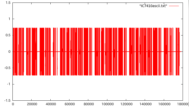
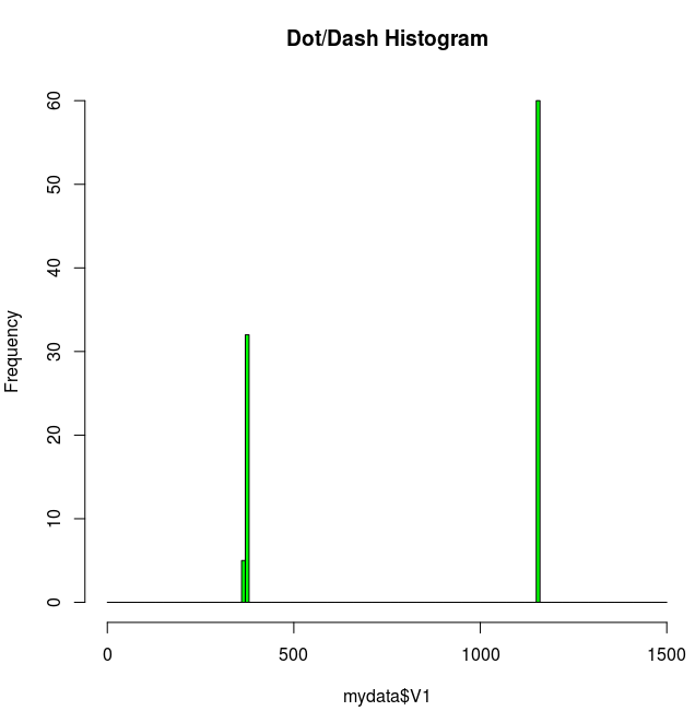
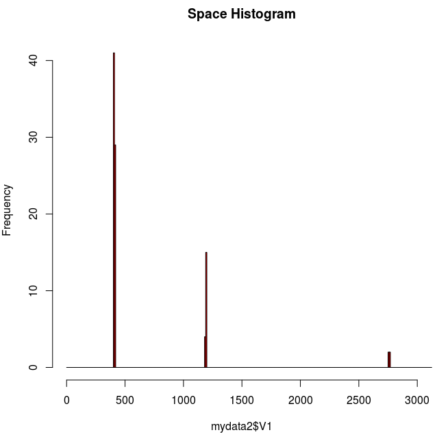
This is a histogram for the spaces.

> space1=subset(mydata2$V1,mydata2$V1<750)
> space3=subset(mydata2$V1,mydata2$V1>750 & mydata2$V1<2000)
> space7=subset(mydata2$V1,mydata2$V1>2000)
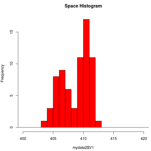
> mean(space1)
[1] 409.2429
> mean(space3)
[1] 1192.263
> mean(space7)
[1] 3935.857
> sd(space1)
[1] 2.337072
> sd(space3)
[1] 2.490919
> sd(space7)
[1] 1466.553
> mean(space7)/mean(space1)
[1] 9.617412
> mean(space3)/mean(space1)
[1] 2.913339
> space7
[1] 2762 2758 2757 2763 5503 5505 5503

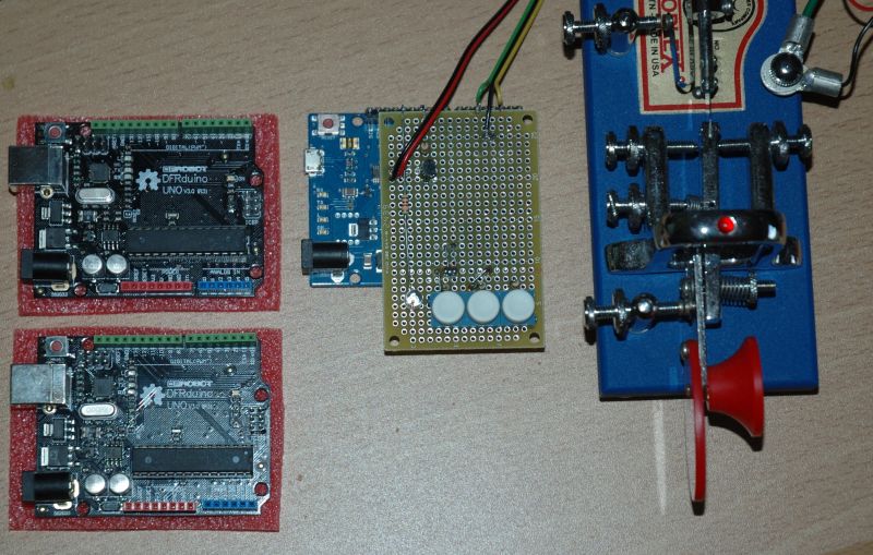
The three large values (5503, 5505, and 5503, not shown in the histogram due to out of the range) for the space7 is perhaps due to the Logger32 macro command I wrote, in which strings to transmit, “CQ CQ CQ de …”, is divided into several lines.

> space7=subset(mydata2$V1,mydata2$V1>2000 & mydata2$V1<3000)
> mean(space7)
[1] 2760
> sd(space7)
[1] 2.94392
> mean(space7)/mean(space1)
[1] 6.744162

capture_001_16042014_132041

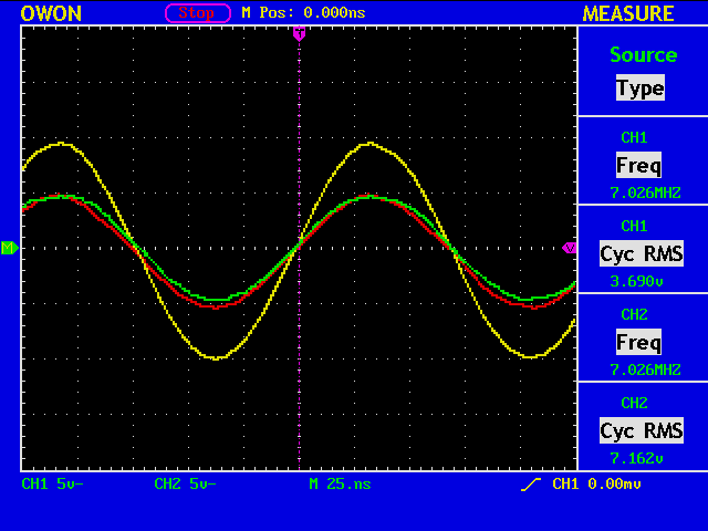
Of course, we must check if this variation comes from the Keyer output or from, for example, slicing the envelope of the side-tone.

My Keying (6)

envelope

A side-tone signal (500Hz) for the letter “A”, and its envelope.

envelope2

The sampling frequency is 8kHz, 16 times the side-tone frequency, and the envelope is computed as:
env(nT) = x(nT)^2 + x((n-4)T)^2

capture_003_13042014_131737

This is a histogram when the ASCII code string for “CQ CQ CQ de …” is sent to the rig (IC-7410) from Logger32 via USB I/F.

% R
> mydata<-read.table("H.txt")
> mydata
     V1
1  1159
2   376
3  1159
4   375
5  1159
> th=seq(0,1500,10)
> hist(mydata$V1,xlim=c(0,1500),breaks=th,main="Dot/Dash Histogram",col="green")
> dash=subset(mydata$V1,mydata$V1>750)
> mean(dash)
[1] 1158.167
> sd(dash)
[1] 2.084378
> dot=subset(mydata$V1,mydata$V1<750)
> mean(dot)
[1] 374.5946
> sd(dot)
[1] 2.127328
> length(dash)
[1] 60
> length(dot)
[1] 37
> mean(dash)/mean(dot)
[1] 3.091787

The dot-to-dash ratio does not become exactly 3.0, because some systematic offset is introduced to both length when quantizing the envelope.

Arduino-compatible Boards (2)

uno1

It seems that my Uno compatible board is working O.K. with K3NG CW Keyer software. But while using the Leonardo board, I was thinking that the baud rate of the serial port was 9600bps. The truth is that I was just being lucky?

uno2

Arduino Leonardo (11)

k3ngIe2

Since the Autospace feature is ON, if there is a space between the two letters longer than one element, a letter space is automatically inserted between “i” and “e”.

k3ngIe

If there is no such space, no letter space is inserted, and the keyer output becomes “s” instead of “ie”.

k3ngEee

One more example of “eee”, being autospaced.

Arduino Leonardo (10)

k3ngR

K3NG CW keyer using an Arduino Leonardo board. The red trace shows the keyer output for the letter “R”, and the yellow trace shows the closure of the dot contact. Note that the voltage 3.3V (red) comes from my rig, IC-7410, while the voltage 5.0V (yellow) comes from the Leonardo board.

\s

Iambic B
WPM: 24
Dah to dit: 3.00
Weighting: 50
Autospace On
Wordspace: 7
TX: 1

The dot duration is exactily 50mS, because the speed is set to 24wpm. (Note: 1.0/(24*50/60)=50mS.) You can also see Iambic mode B is employed from the fact that the dot contact is released while sending a dash.

k3ngR2

One more figure, when I tried to release the dot paddle very early, but still sending “R”.

Arduino-compatible Boards

DSC_9494_rot

I purchased two Arduino Uno compatible boards, which are on the pink sheet. In the center is an Arduino Leonard with a small interface board plugged on top. Currently it is used as a K3NG CW keyer. The keying output of the keyer is connected to my Vibroplex in parallel so that I can use either a paddle (not shown in ghe figure) or a bug.

I think I am going to make another K3NG keyer with newly obtained boards, which will hopefully be somewhat better looking than my first work.

Toroidal Cores (3)

DSC_9489_crop

What we would like to know is how the troidal inductors works at not 100kHz, but at some practical frequencies, say, 7026kHz. So here comes our good old impedancen bridge.

The inductance should be around 116uH with 10 turns, which should turn out to be 5.12kohm at 7026kHz.

troid7026

gnuplot> load "gnuplot11.txt"
Freq [MHz]=7.026
V1=3.69
V2=7.162
Cursor 1=1.6e-09
Cursor 2=0.0

vratio=1.94092140921409
phase1 [deg]=4.046976
phase2 [deg]=0.0

abs(gamma)=0.946050942356418
swr=36.0720099174506
cz={229.743717103124, 599.501591363751}

capture_002_05042014_124952

capture_001_05042014_124935

It is somewhat difficult to measure such high impedance with accuracy, because the system impedance is only 50ohm.