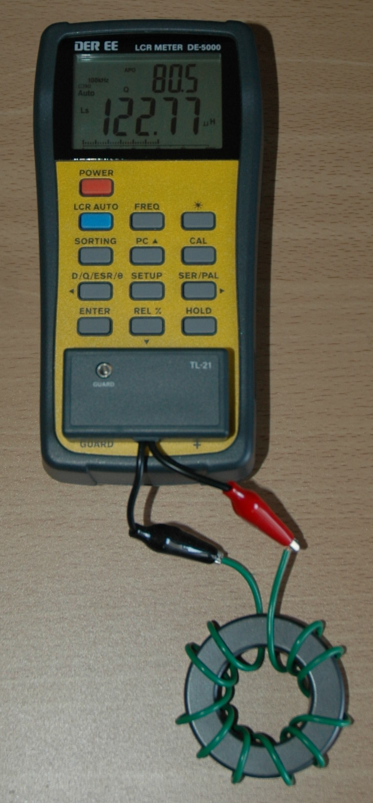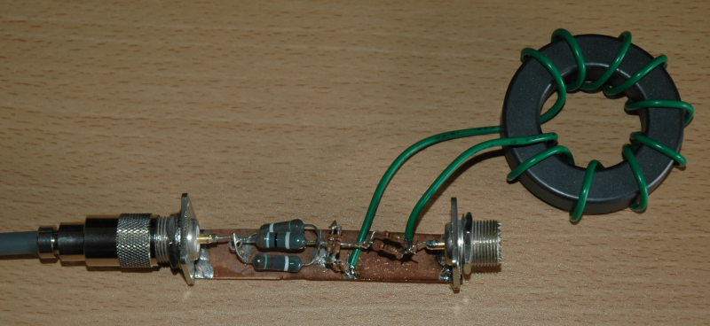
What we would like to know is how the troidal inductors works at not 100kHz, but at some practical frequencies, say, 7026kHz. So here comes our good old impedancen bridge.
The inductance should be around 116uH with 10 turns, which should turn out to be 5.12kohm at 7026kHz.
gnuplot> load "gnuplot11.txt"
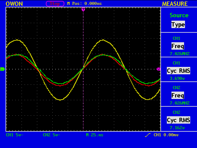
Freq [MHz]=7.026
V1=3.69
V2=7.162
Cursor 1=1.6e-09
Cursor 2=0.0
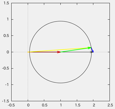
vratio=1.94092140921409
phase1 [deg]=4.046976
phase2 [deg]=0.0
abs(gamma)=0.946050942356418
swr=36.0720099174506
cz={229.743717103124, 599.501591363751}
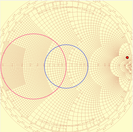
It is somewhat difficult to measure such high impedance with accuracy, because the system impedance is only 50ohm.