The site, M3GHE on radio was very helpful.

Ham Radio Blog
The site, M3GHE on radio was very helpful.
FAQ
Q: Can I listen to Wide FM radio stations?
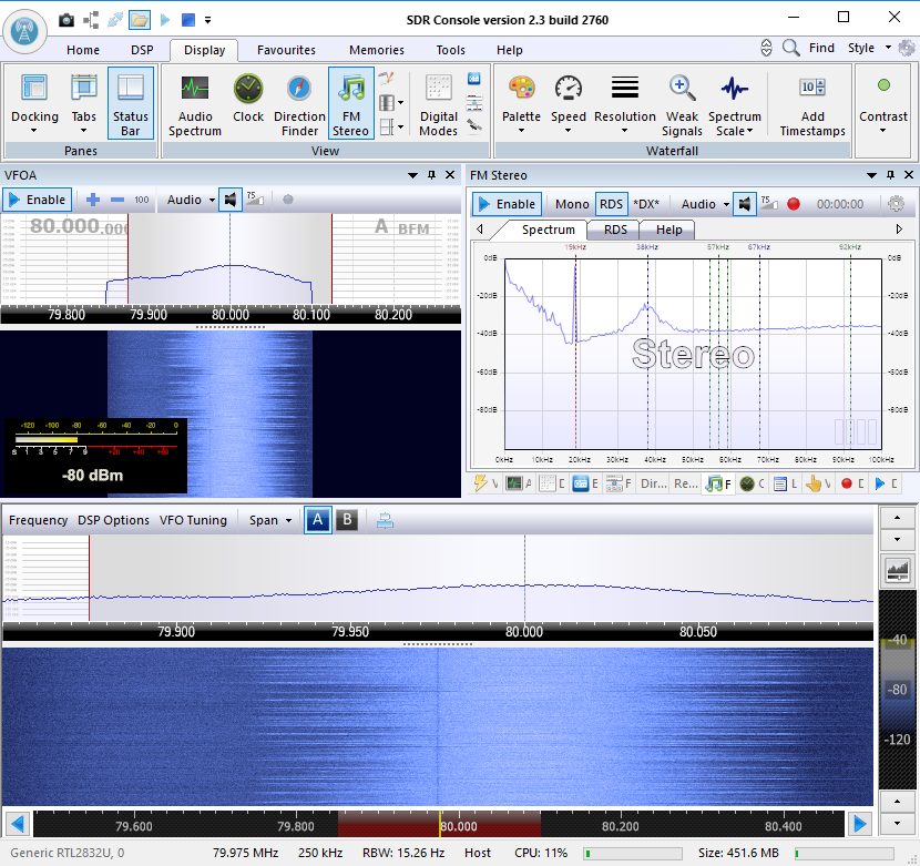
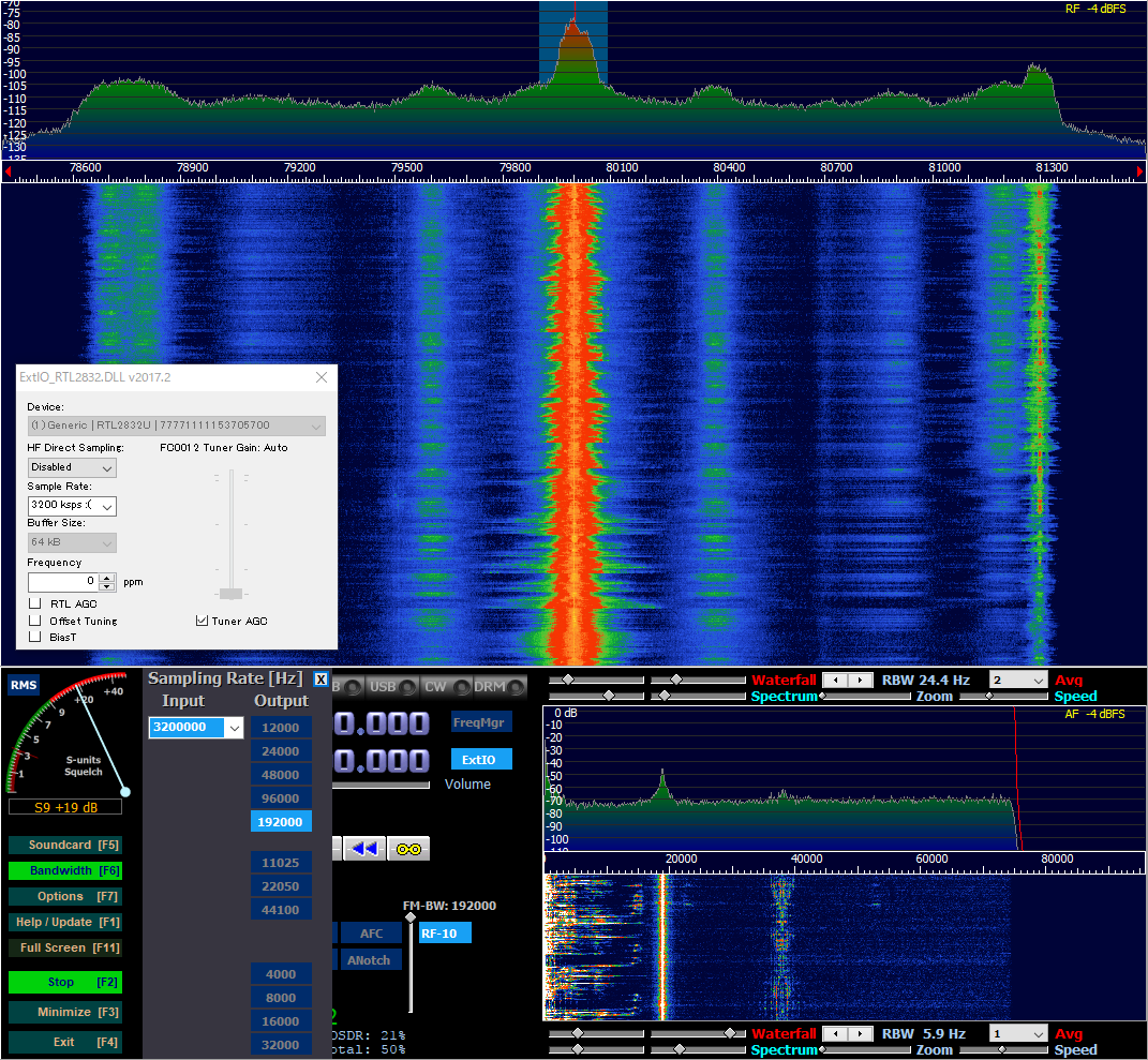
A: Yes. Currently, this can be achieved by using a workaround procedure as described below. Switch to FM and use the ‘Bandwidth’ button to increase the output sampling rate to at least 96000 Hz. We will endeavor to provide better support for the Wide FM mode in a future version of HDSDR.
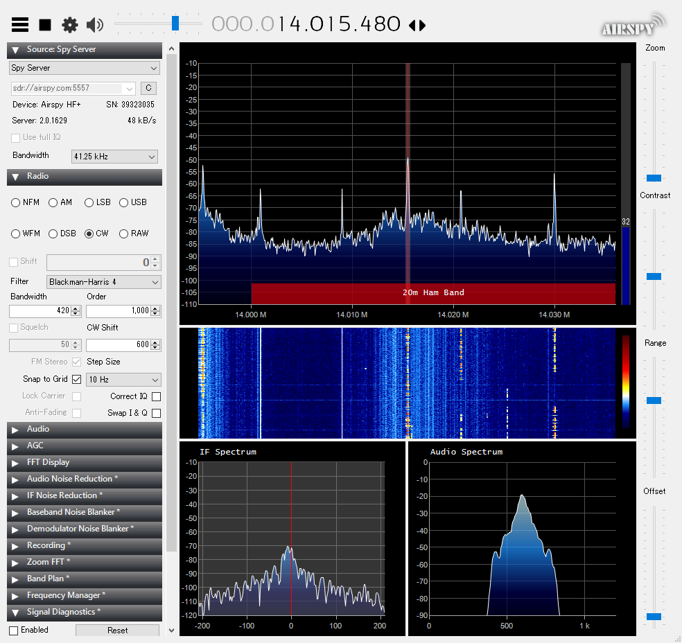
SPY Server is a yet another SDR server, but unlike other Web SDR servers it requires the software SDR# for a client.
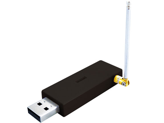
I am using DT-305BK sold as a tuner for terrestrial digital video broadcasting in Japan.
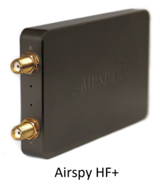
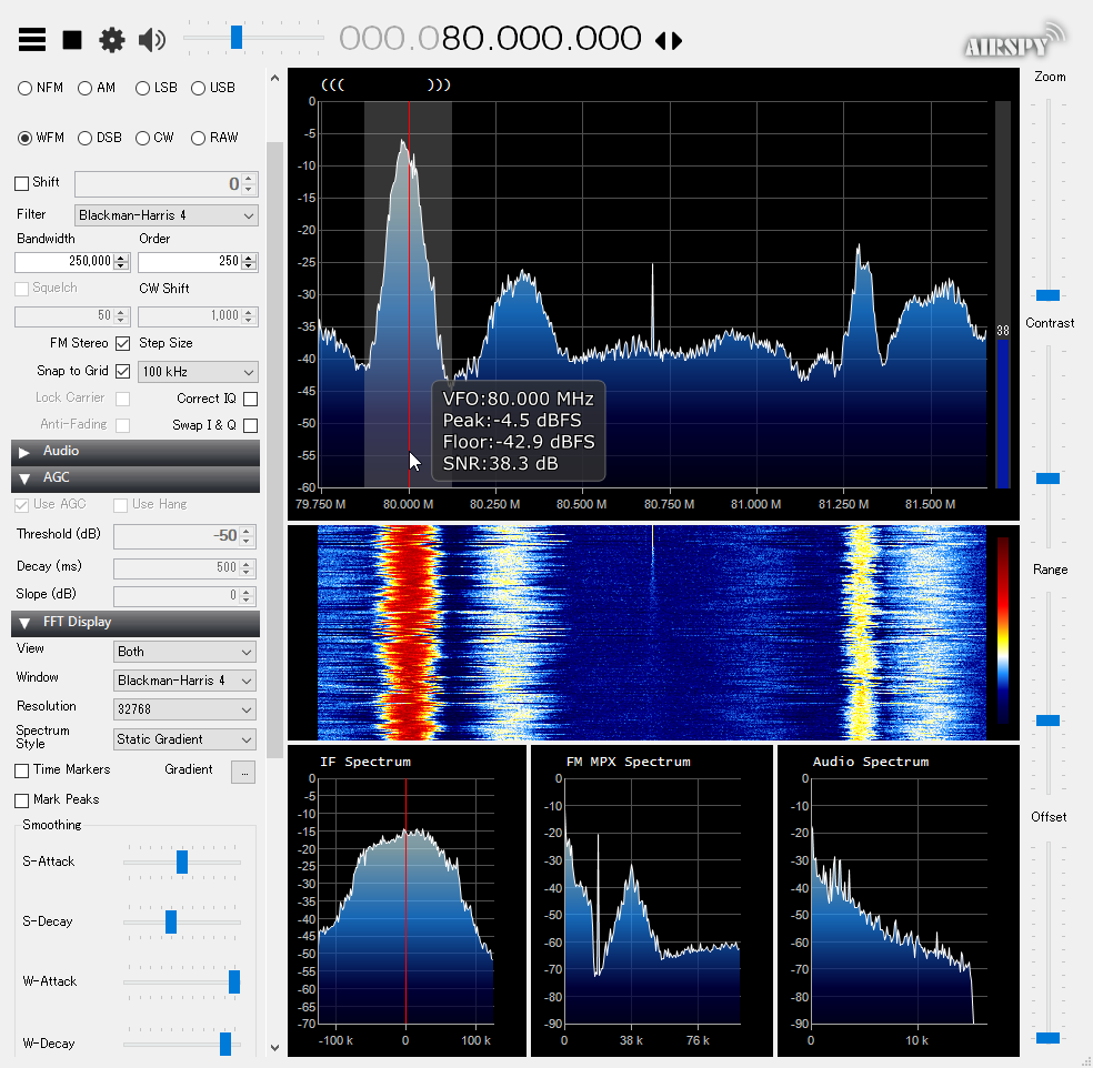
Airspy HF+ is a low cost SDR for HF and VHF bands.
One of the features of the receiver, they claim, is that a polyphase harmonic rejection mixer is employed.
So what exactly is that mixer? The followings are what I have gathered so far.

First, the WIPO publication WO 2010/089700 A1.
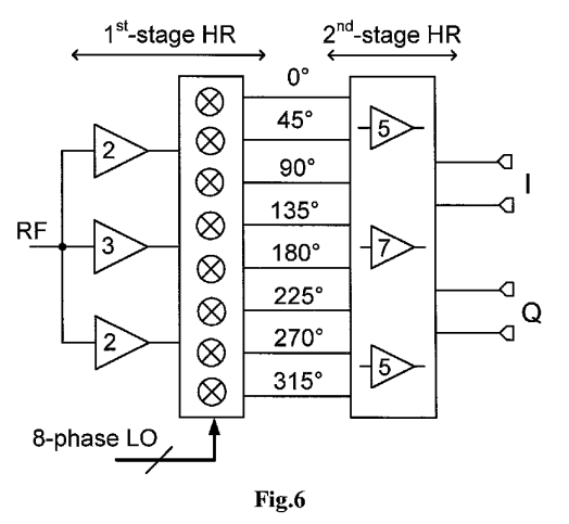
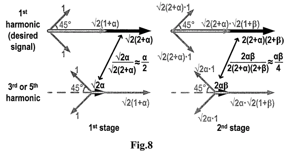
The document discloses a two-stage polyphase harmonic rejection mixer.
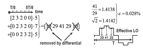
The set of the coefficients {2, 3, 2} and {5, 7, 5} generates the amplitude ratio of 41/29 (=1.4138) which approximates the desired sqrt(2) quite closely.
The effect is the cancellation of 3rd and 5th order harmonics.
Next, the dissertation by Rafi.
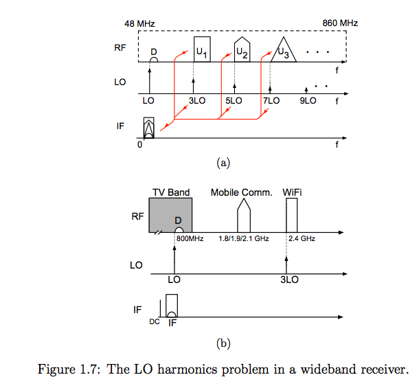
The figure shows why the LO harmonics must be suppressed if one wants to avoid using (tunable) RF filters.
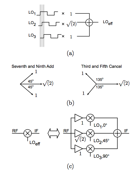
This is Fig. 2.7, and shows the basic concept of harmonic rejection mixers.
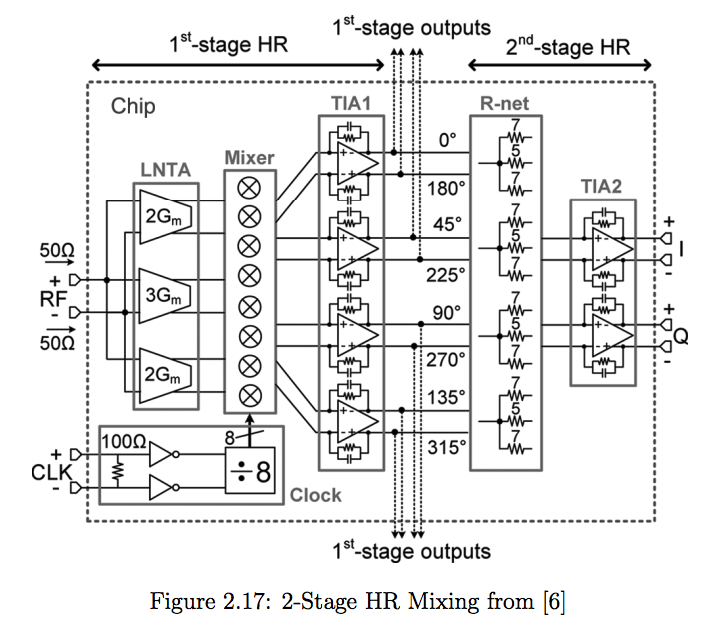
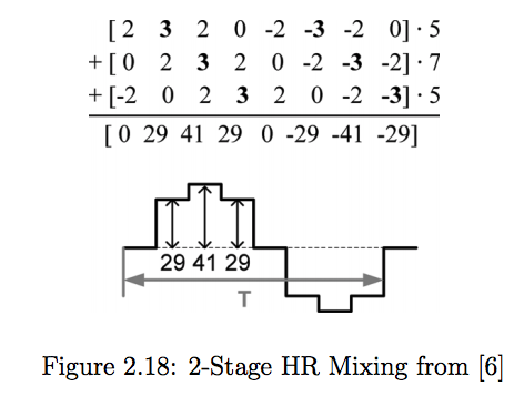
The above two figures are from [6];
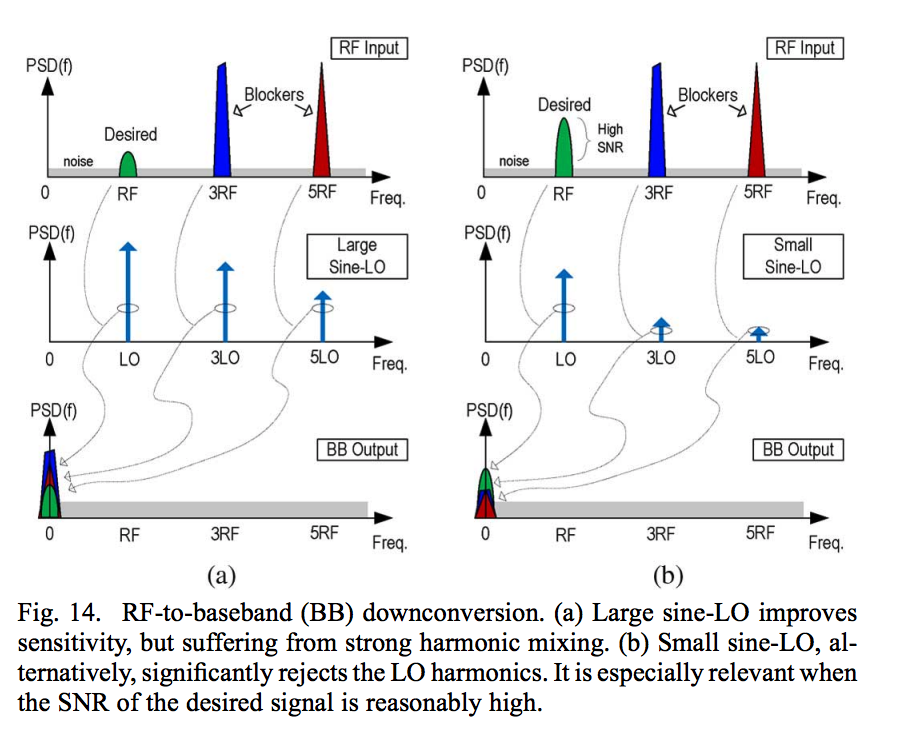
Finally, yet another nice figure showing the effect of LO harmonics from the paper, A Sine-LO Square-Law Harmonic-Rejection Mixer—Theory, Implementation, and Application.
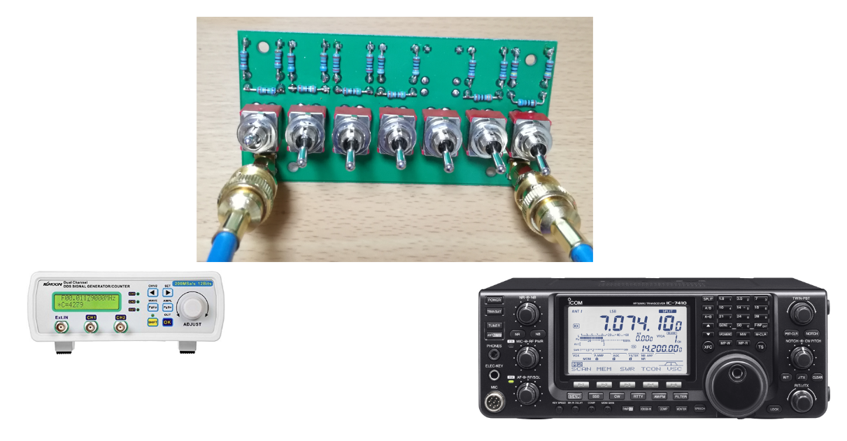
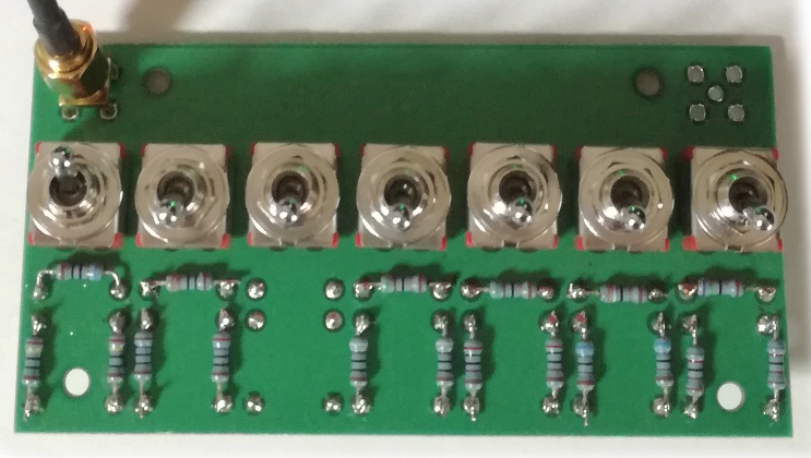
A step attenuator with the 1dB/step variations.
I am tentatively using the conversion function:
def s_meter2db(s_meter): # S0=000, S9=120, S9+60dB=240; S9=-73dBm
	if s_meter < 120:
		s_meter_db = 0.2 * (s_meter - 120.0) - 73.0
	else:
		s_meter_db = 0.5 * (s_meter - 120.0) - 73.0
	return s_meter_db
6 / 11
: Change settings and Hit return to continue..
irep =  5
freq[kHz] = 6000.0 170 -48.0 [dBm]
freq[kHz] = 6200.0 170 -48.0 [dBm]
freq[kHz] = 6400.0 170 -48.0 [dBm]
freq[kHz] = 6600.0 170 -48.0 [dBm]
freq[kHz] = 6800.0 170 -48.0 [dBm]
freq[kHz] = 7000.0 170 -48.0 [dBm]
freq[kHz] = 7200.0 170 -48.0 [dBm]
freq[kHz] = 7400.0 170 -48.0 [dBm]
freq[kHz] = 7600.0 170 -48.0 [dBm]
freq[kHz] = 7800.0 170 -48.0 [dBm]
7 / 11
: Change settings and Hit return to continue..
irep =  6
freq[kHz] = 6000.0 168 -49.0 [dBm]
freq[kHz] = 6200.0 168 -49.0 [dBm]
freq[kHz] = 6400.0 168 -49.0 [dBm]
freq[kHz] = 6600.0 168 -49.0 [dBm]
freq[kHz] = 6800.0 168 -49.0 [dBm]
freq[kHz] = 7000.0 168 -49.0 [dBm]
freq[kHz] = 7200.0 168 -49.0 [dBm]
freq[kHz] = 7400.0 168 -49.0 [dBm]
freq[kHz] = 7600.0 168 -49.0 [dBm]
freq[kHz] = 7800.0 168 -49.0 [dBm]
8 / 11
: Change settings and Hit return to continue..
irep =  7
freq[kHz] = 6000.0 166 -50.0 [dBm]
freq[kHz] = 6200.0 166 -50.0 [dBm]
freq[kHz] = 6400.0 166 -50.0 [dBm]
freq[kHz] = 6600.0 166 -50.0 [dBm]
freq[kHz] = 6800.0 166 -50.0 [dBm]
freq[kHz] = 7000.0 166 -50.0 [dBm]
freq[kHz] = 7200.0 166 -50.0 [dBm]
freq[kHz] = 7400.0 166 -50.0 [dBm]
freq[kHz] = 7600.0 166 -50.0 [dBm]
freq[kHz] = 7800.0 165 -50.5 [dBm]
This is with the step size of 5dB.
Let’s see if I can measure my homebrew step attenuator as if I have an scalar network analyzer.
The following figure shows what a true scalar network analyzer is.
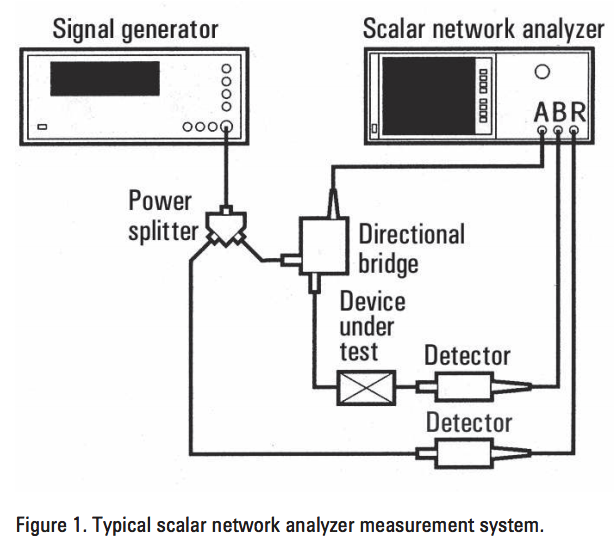
http://literature.cdn.keysight.com/litweb/pdf/5990-4798EN.pdf
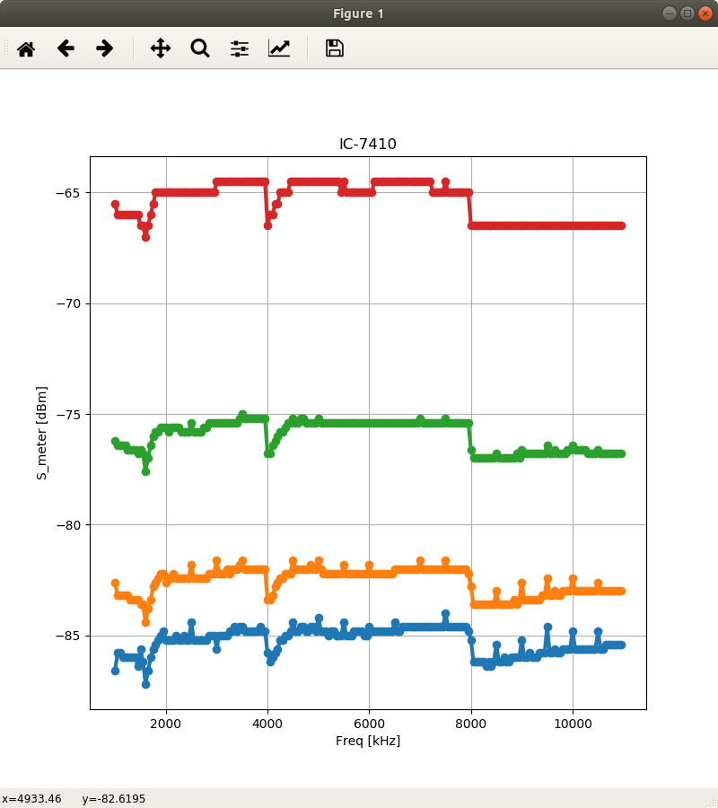
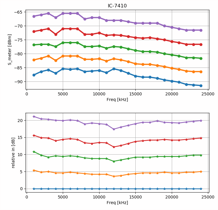
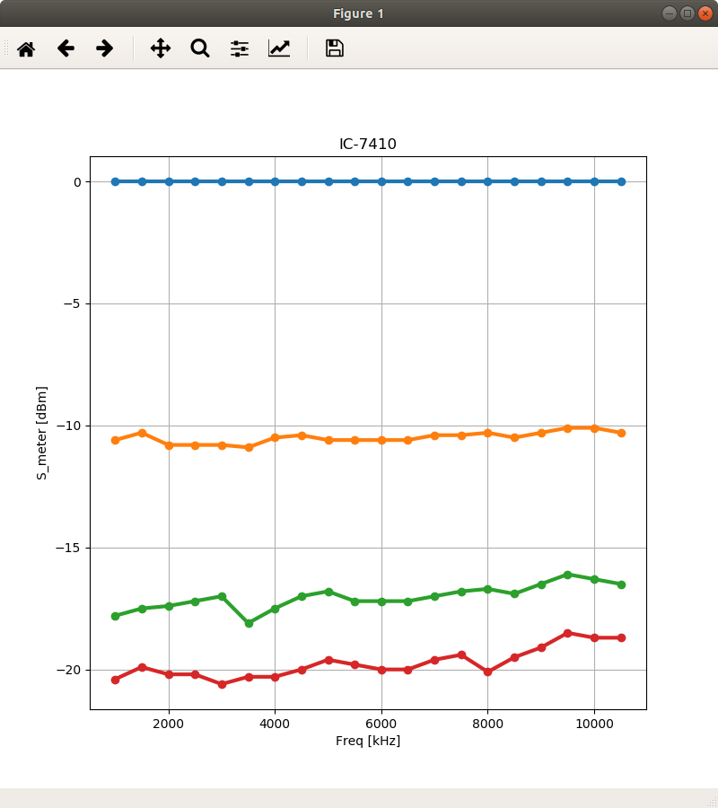
The traces, from top (red) to bottom (blue), correspond to -20dB, -30dB, -37dB, and -40dB positions of the attenuator, respectively.
There is a significant ripple, perhaps due to the fluctuations of either the output level of the SG or the sensitivity of the receiver.
If you normalize the responses assuming that the -40dB response is flat, you will get the following figure.
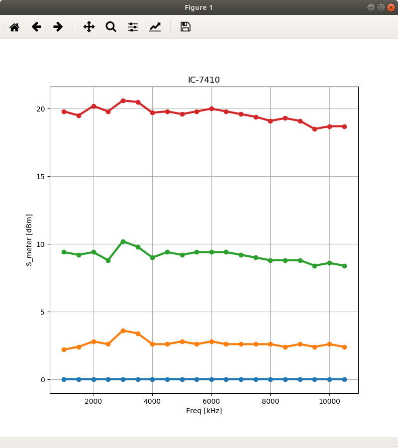
Or the following figure, if the -20dB response is assumed to be flat.
Please also read my article SMA Calibration Kit (2) for the measurement of the same attenuator with AA-30.ZERO.

It seems that the frequency response of the attenuator is reasonably flat up 30MHz.
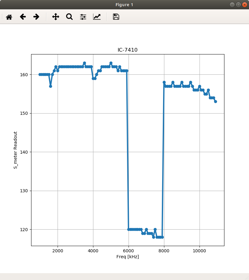
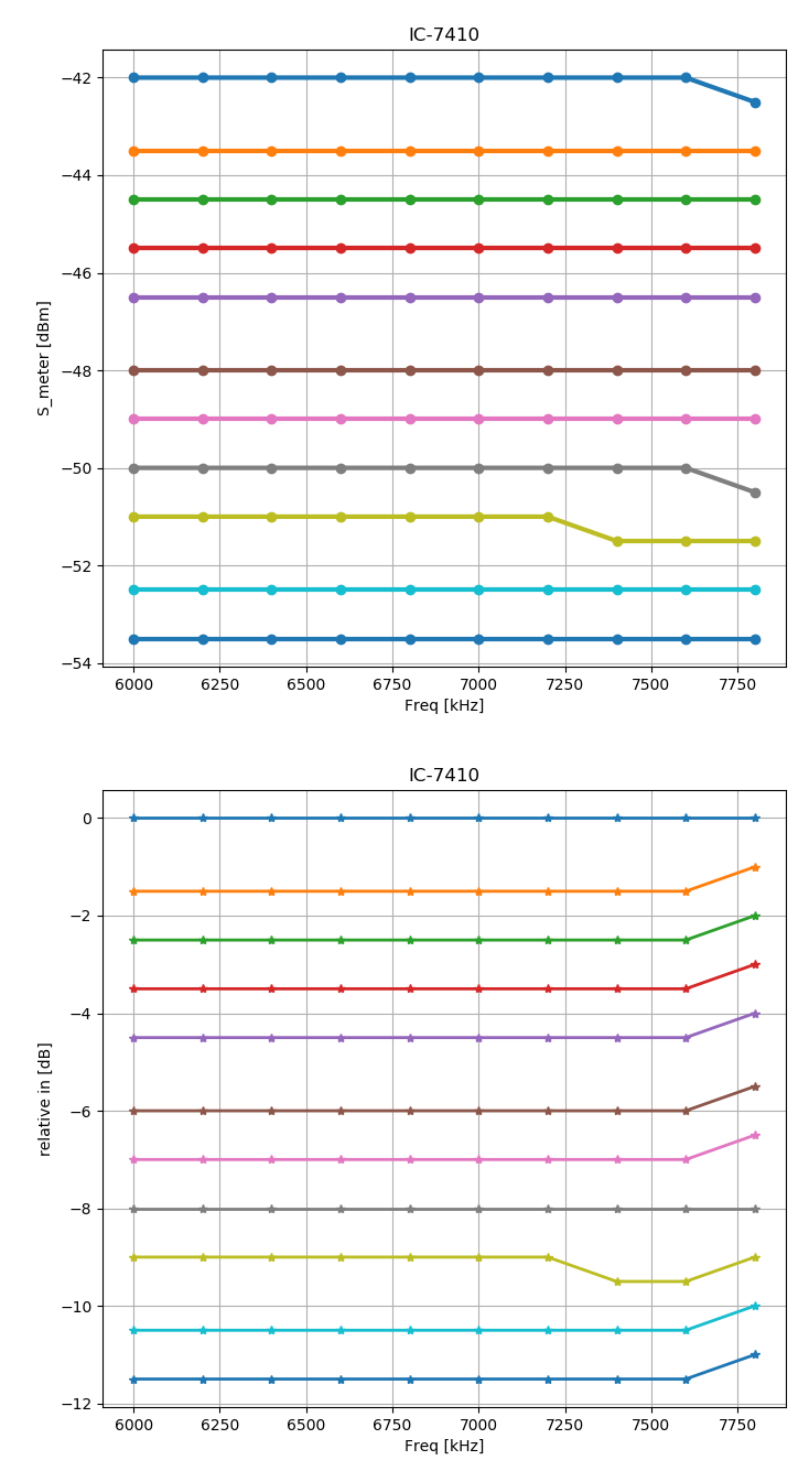
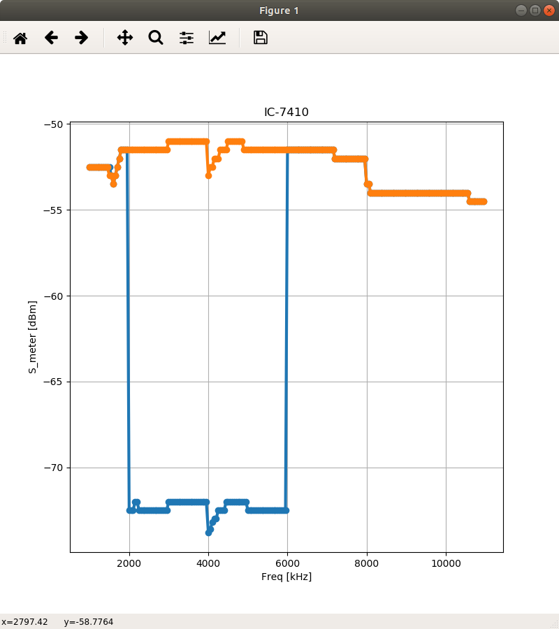
The SG and the receiver are controlled so that the both will track the same frequency over the range from 1MHz to 11MHz.
The dip from 6MHz and 8MHz is due to the RF attenuator of the receiver activated for the 40m band. The receiver has a memory to keep the various settings for each band including the status of the RF ATT.
There is only a step attenuator between the SG and the receiver, so the response should ideally be flat if the RF ATT is never emplyoed for every band.
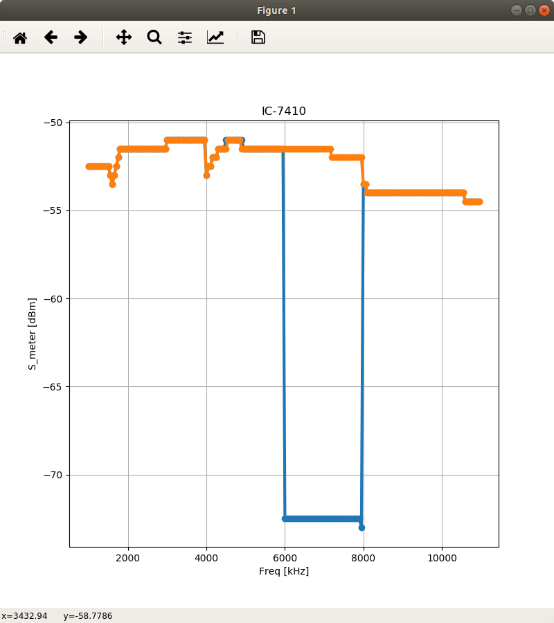
The orange traces is for the case the RF ATT for the 40m band is disabled.
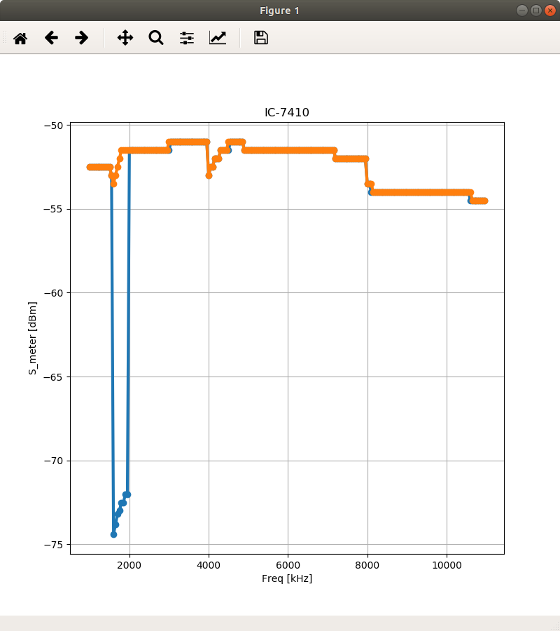
This figure shows when the RF ATT for the 160m band is activated.
This is for the 80m band.
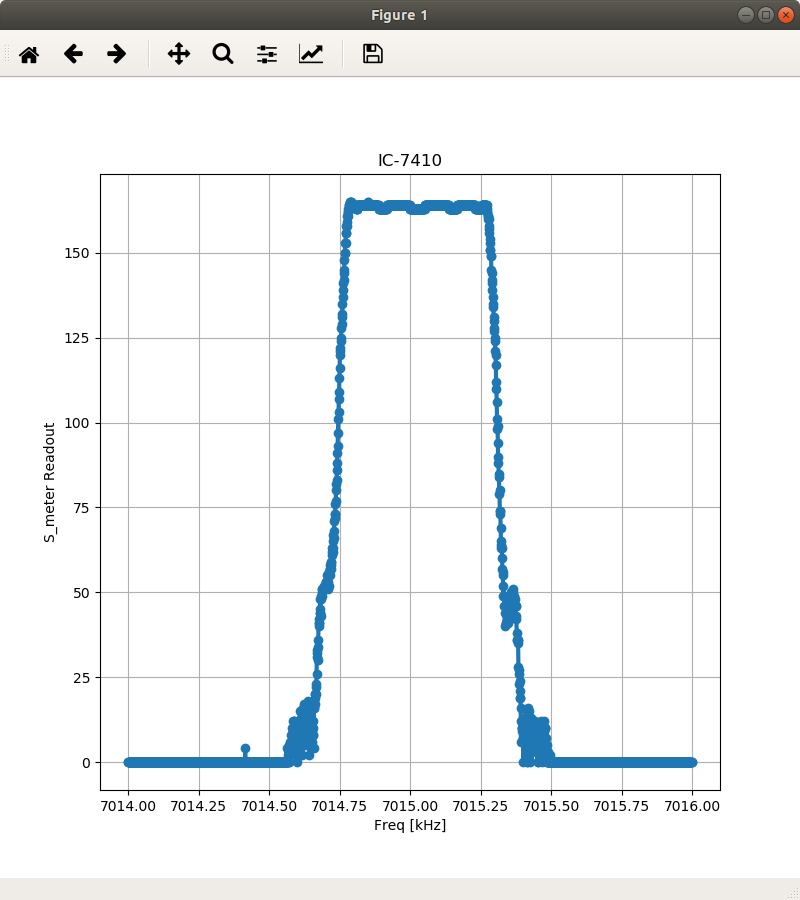
This is when the output frequency of the SG is varied with 1Hz step.The receive frequency of IC-7410 is fixed to 7015kHz.
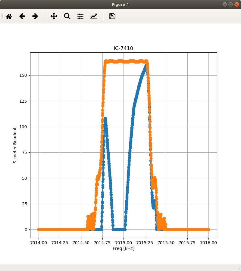
The same configuration but with and without the audio notch filter.
The next question is what happens if both the SG and the receiver frequencies are varied in a synchronized manner.
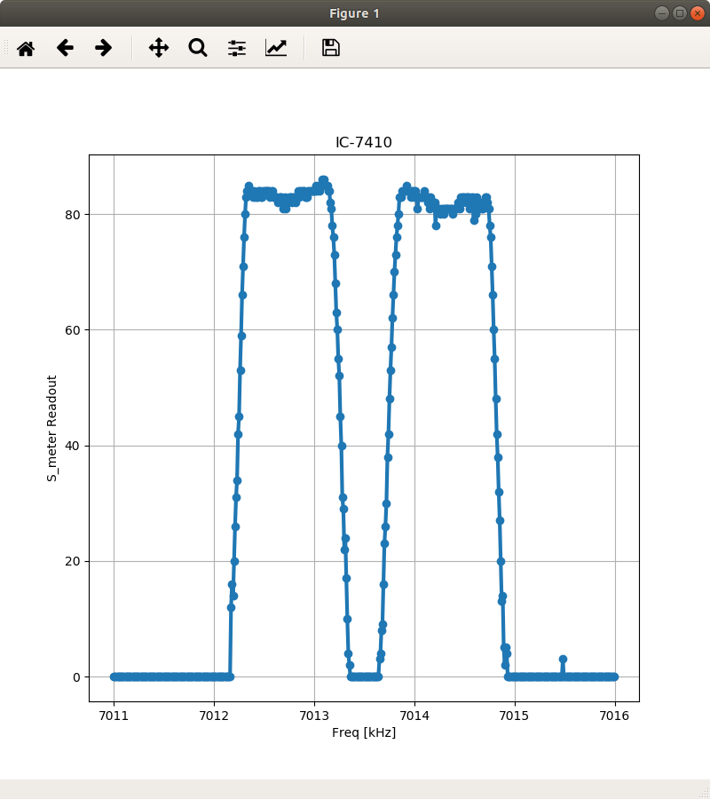
This looks better. An SSB filter and a notch filter.
Now, the output of my toy SG is connected directly to IC-7410 through a homebrew step attenuator.
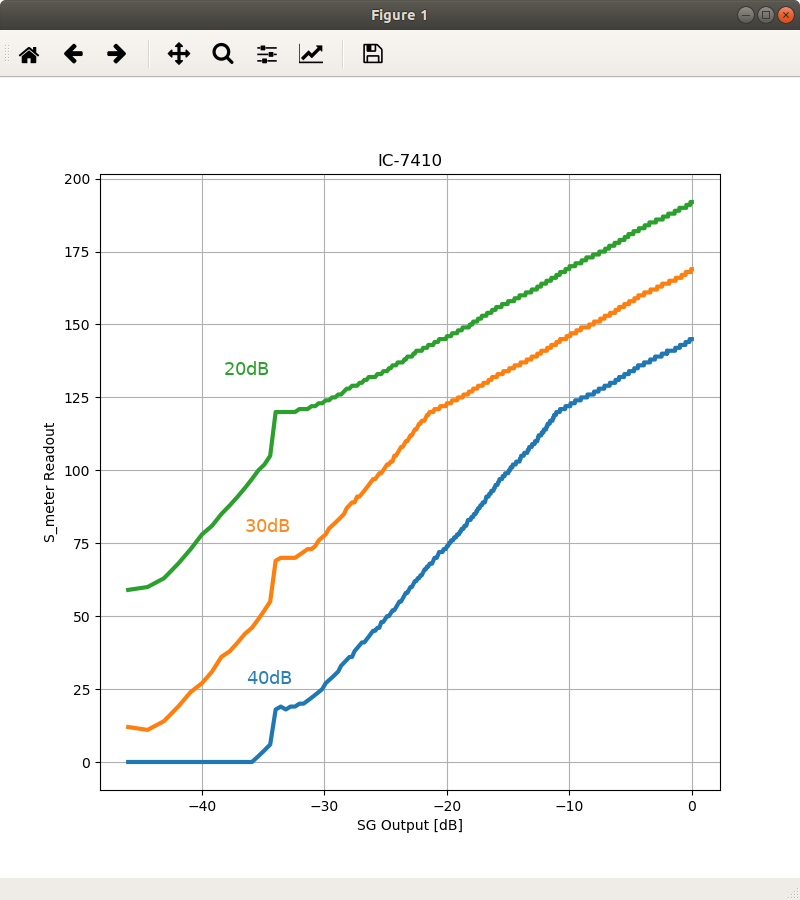
The graph corresponds to three different positions of the attenuator.
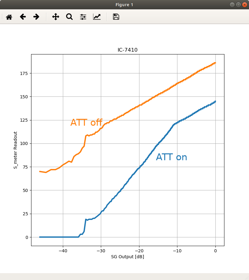
This is with the RF attenuator of IC-7410 on and off, respectively.
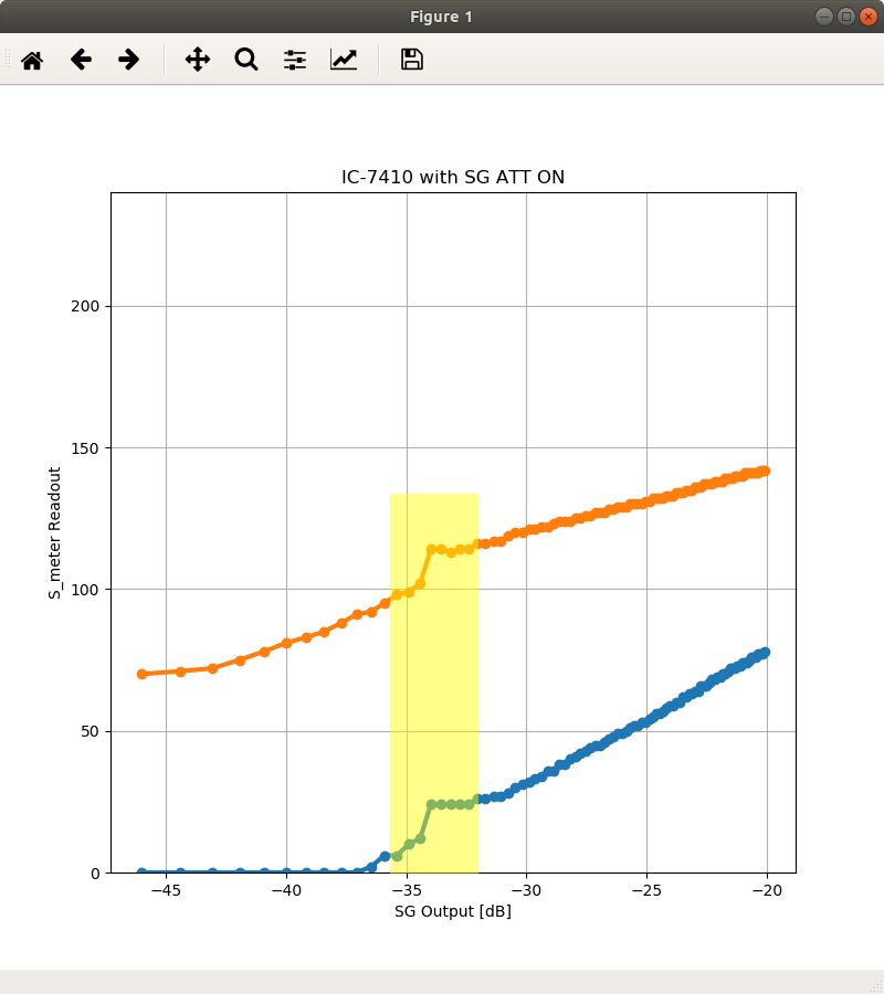
It seems that the output of the SG jumps around -34 dB. This is not due to the receiver, because it always happens with the same output level of the SG.