Rig Control with pySerial (3)

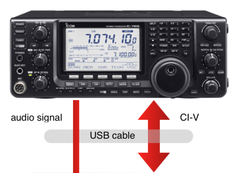
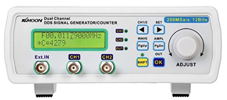
My signal generator can be controlled with a PC using its USB I/F.

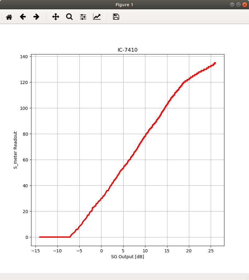
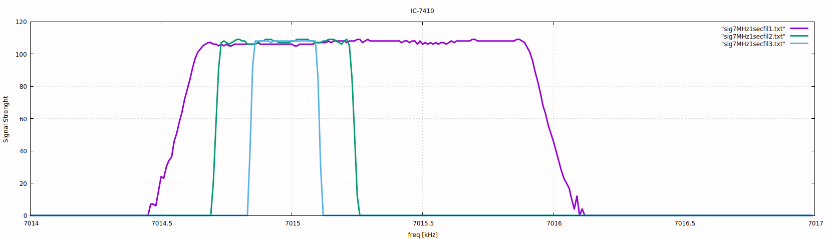
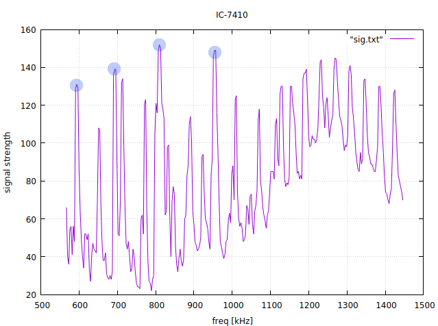
The graph shows the S_meter readout of IC-7410 when the output level of the SG is varied from 0.2 Vpp to 20 Vpp with the step size of 20 mVpp.

Note that the signal is not directly connected, but only loosely coupled.

The readout should be 000 for S0, 120 for S9, and 240 for S9+60dB, according to the equipment manual.

import sys
import math
from time import sleep
import numpy as numpy
import matplotlib.pyplot as plt
import serial

ser_sg = serial.Serial('/dev/ttyUSB0', 57600, timeout=1) # signal generator
ser_rx = serial.Serial('/dev/ttyUSB1', 19200, timeout=1) # receiver

ser_sg.write(b':\n')
s = ser_sg.read(99)
print('[:]              ', s)

ser_sg.write(b':r0c\n')
s = ser_sg.read(99)
print('[:r0c]           ', s)

ser_sg.write(b':r1c\n')
s = ser_sg.read(99)
print('[:r1c]           ', s)

ser_sg.write(b':r2c\n')
s = ser_sg.read(99)
print('[:r2c]           ', s)

ser_sg.write(b':s1f0701500000\n')
s = ser_sg.read(99)
print('[:s1f0701500000] ', s)

ser_sg.write(b':r1f\n')
s = ser_sg.read(99)
print('[r1f]            ', s)

ser_sg.write(b':s1a020\n')
s = ser_sg.read(99)
print('[s1a0123]        ', s)

ser_sg.write(b':r1a\n')
s = ser_sg.read(99)
print('[r1a]            ', s)

freq_10hz = 701500
hz10   = freq_10hz           % 10
hz100  = freq_10hz //     10 % 10
khz    = freq_10hz //    100 % 10
khz10  = freq_10hz //   1000 % 10
khz100 = freq_10hz //  10000 % 10
mhz    = freq_10hz // 100000 % 10

set_freq = b'\xfe\xfe\x80\xe0\x05'     \
		+bytes([16*hz10        ])      \
		+bytes([16*khz   +hz100])      \
		+bytes([16*khz100+khz10])      \
		+bytes([          mhz  ])      \
		+b'\x00\xfd'
ser_rx.write(set_freq)
data1 = ser_rx.read(18) # not 17 to raise timeout

xvalue = []
yvalue = []

for amp_10mv in range(20, 2002, 2):
	stramp = str(amp_10mv)
	set_amp = b':s1a'+bytes(stramp.encode())+b'\n'
	print(amp_10mv, stramp, bytes(stramp.encode()), set_amp)
	ser_sg.write(set_amp)
	sleep(0.5)
	
	get_Smeter = b'\xfe\xfe\x80\xe0\x15\x02\xfd'
	ser_rx.write(get_Smeter)
	data2 = ser_rx.read(16)
	signal = int( data2.hex()[26:30] )
	amp = amp_10mv/100.0
	ampdB = 20.0 * math.log10(amp)
	xvalue.append(ampdB)
	yvalue.append(signal)
	print(amp, ampdB, signal)

ser_sg.close()
ser_rx.close()

plt.figure(1, figsize=(8,8))
plt.subplot(111)
plt.grid(True)
plt.plot(xvalue, yvalue, color='red', linewidth=3)
plt.title('IC-7410')
plt.xlabel('SG Output [dB]')
plt.ylabel('S_meter Readout')
plt.show()

Rig Control with pySerial (2)

With a signal generator, you can measure the characteristics of your IF filters.

The output of the signal generator, 7015kHz CW, is loosely coupled to IC-7410, and the signal strength is observed while tuning the receiver from 7014kHz to 7016.5kHz with the step size of 100Hz.

import sys
import numpy as numpy
import matplotlib.pyplot as plt
import serial

ser = serial.Serial('/dev/ttyUSB0', 19200, timeout=1)

xvalue = []
yvalue = []

for freq_10hz in range(701400, 701650, 1):
	hz10   = freq_10hz           % 10
	hz100  = freq_10hz //     10 % 10
	khz    = freq_10hz //    100 % 10
	khz10  = freq_10hz //   1000 % 10
	khz100 = freq_10hz //  10000 % 10
	mhz    = freq_10hz // 100000 % 10

	set_freq = b'\xfe\xfe\x80\xe0\x05'     \
			+bytes([16*hz10        ])      \
			+bytes([16*khz   +hz100])      \
			+bytes([16*khz100+khz10])      \
			+bytes([          mhz  ])      \
			+b'\x00\xfd'
	ser.write(set_freq)
	data1 = ser.read(18) # not 17 to raise timeout
	
	get_Smeter = b'\xfe\xfe\x80\xe0\x15\x02\xfd'
	ser.write(get_Smeter)
	data2 = ser.read(16)
	signal = int( data2.hex()[26:30] )
	freq = freq_10hz/100.0
	xvalue.append(freq)
	yvalue.append(signal)
	print(freq, signal)

ser.close()

plt.figure(1, figsize=(8,8))
plt.subplot(111)
plt.grid(True)
plt.plot(xvalue, yvalue, color='red', linewidth=3)
plt.show()

The receiver has three difital IF filters, each with presettable bandwidth. The graph shows my current settings.

Rig Control with pySerial

Let’s write a rig control program with pySerial.

import serial
ser = serial.Serial('/dev/ttyUSB0', 19200, timeout=1)

for freq_khz in range(567,1449,3):
	khz    = freq_khz         % 10
	khz10  = freq_khz //   10 % 10
	khz100 = freq_khz //  100 % 10
	mhz    = freq_khz // 1000 % 10

	set_freq = b'\xfe\xfe\x80\xe0\x05\x00' \
			+bytes([16*khz         ])      \
			+bytes([16*khz100+khz10])      \
			+bytes([          mhz  ])      \
			+b'\x00\xfd'
	ser.write(set_freq)
	data1 = ser.read(18) # not 17 to raise timeout
	
	get_Smeter = b'\xfe\xfe\x80\xe0\x15\x02\xfd'
	ser.write(get_Smeter)
	data2 = ser.read(16)

	print(freq_khz, int( data2.hex()[26:30] ))
ser.close()

A simple program to scan the AM band and to record the signal strength.

The stations are, from left to right, NHK-1, NHK-2, AFN, and TBS.

A Small Loop Antenna for Receive Only (2)

The antenna with VC sections C1 and C2 in parallel is tunable between 4.030MHz and 9.860MHz as is expected from the following tables.

Measured capacitance of each section of the VC
       min       center	     max
----------------------------------
c1  148.4pF      62.6pF    22.0pF
c2  150.3pF      65.9pF    23.5pF
c3   40.7pF      27.8pF    19.9pF
c4   40.4pF      26.9pF    19.8pF
with L=5.1uH, the capacitance should be:
 3.5MHz   7MHz  10MHz  14MHz  18MHz  21MHz  25MHz  28MHz
-------------------------------------------------------
  405pF  101pF   50pF  25pF   15pF    11pF    8pF    6pF

A Small Loop Antenna for Receive Only

Here is my first small loop antenna. Small means that the loop circumference is around 10% of the operating wavelength.

I intended to use the antenna on the 40m band, so I cut my old coaxial cable for TV antenna to 4.5m and used only the blade. The shape of the loop could be almost anything, and I made it a triangle so that the T shaped wooden structure can support the loop.

The measured inductance of the 4.5m length loop turned out to be 5.1uH, so the capacitance should be around 100pF to get the resonant frequency of 7MHz.

I used a tiny tuning capacitor for AM/FM radios with four sections, 160pF x 2 and 40pF x 2, starting my experiment with just two 160pF sections in parallel.

The coupler is a one-turn to eight-turn transformer with FT-140-43.

This what I get. Note that the resonance is very sharp, and if you scan the frequency range coarsely, you will easily miss the point.

Not very bad for a first trial, isn’t it?

Some of the stations received with FT8 while the antenna is still in the shack.

Former Joint Chiefs chairman worries..

https://edition.cnn.com/videos/tv/2018/04/06/exp-gps-0408-mullen-sot-generals.cnn

Former Joint Chiefs chairman worries about generals in Trump’s White House
By Kate Sullivan
Updated 6:17 PM ET, Sun April 8, 2018

(CNN) — Retired Adm. Mike Mullen, a former chairman of the Joint Chiefs of Staff under Presidents George W. Bush and Barack Obama, said Sunday on CNN’s “Fareed Zakaria GPS” that he has been “extremely concerned” about military officials like retired Gen. John Kelly acting in political roles in President Donald Trump’s administration.

Mullen said he worries that having military officials, “without being a politician, without running for office,” acting politically could undermine the military as an apolitical institution.

Specifically, he said, he worries a “great deal” about Kelly “indirectly undermining us as a military” because of his role as White House chief of staff, a highly political job.

While many people have told him they have felt comfortable having Secretary of Defense James Mattis, Kelly, and former White House national security adviser H.R. McMaster in Trump’s administration, all of whom have been generals, “I don’t share that comfort,” Mullen said.

Mullen said he’s been to countries where the generals and admirals are in charge, which some of the public find comforting, and those are not countries Americans would want to grow up in.

“It’s much more a strongman’s country than it is a democratic, open, free country,” he said.

Mattis, Kelly and McMaster “are not politicians, but they’re operating in this political world inside the White House,” said Mullen, who served four years under two presidents, adding he understands that world well.

“It is a tough, difficult, political environment,” he said, and “it can be very toxic, and it can destroy people.”

McMaster was recently ousted as Trump’s national security adviser; his last day at the White House was Friday. Meanwhile, CNN has reported on tensions between the President and Kelly, who has become the subject of reports saying his influence in the White House is diminished. Trump on Sunday denied that was the case in a tweet criticizing The Washington Post’s reporting on the matter.

Mullen added that he was distressed to see Kelly, a retired four-star general, talk to the press about his experience with the death of his son in Afghanistan as part of an attempt to counter criticisms of Trump’s conversation with a widow of a soldier killed in an ISIS ambush in Niger last year.


“To see John Kelly — and I’ll be very specific — politicize, you know, the death of his son to support the political outcome for the President was very, very distressing to me,”
(emphasis added) Mullen said.

It speaks to the power of that environment, he said, and “the lack of understanding that any of us in the military have about that environment until we get in it and have to operate in it.”

“We are apolitical,” Mullen said about his fellow military service members. “I get that when we take our uniform off we’re citizens,” he added, but “he’s referred to as General Kelly, not Mr. Kelly, for a reason.”

WSJT-X and Qt

The graphical user interfaces (GUIs) for WSJT-X are written in C++ and use the Qt framework.

So I thought it might be interesting to use the Qt framework myself, and to rewrite my old programs, such as sprigmm, with Qt’s APIs.

With Ubuntu 17.10, you may encounter a problem that no examples are listed,

or may experience a build error: cannot find -lGL.

Your Rig with USB Audio I/F and Linux Sound System (Audacity)

With Audacity you can record and play the sound from/to your rig through USB I/F.

If your rig is IC-7410, enter set mode and do;

  • 39. USB MOD Level: 50% (as default)
  • 40. DATA OFF MOD: USB
  • 41. DATA MOD: USB

A list of audio devices is available with the Audacity menu bar: Help -> Audio Device Info..

==============================
Device ID: 8
Device name: USB Audio CODEC: - (hw:2,0)
Host name: ALSA
Recording channels: 2
Playback channels: 2
Low Recording Latency: 0.008685
Low Playback Latency: 0.008685
High Recording Latency: 0.034830
High Playback Latency: 0.034830
Supported Rates:
    32000
    44100
    48000
==============================
Selected recording device: 8 - USB Audio CODEC: - (hw:2,0)
Selected playback device: 8 - USB Audio CODEC: - (hw:2,0)
Supported Rates:
    32000
    44100
    48000

In the directory, /proc/asound, you can see more details.

user1@Asrock ~ % ls -l /proc/asound/card2  
total 0
-r--r--r-- 1 root root 0 Apr  5 12:05 id
dr-xr-xr-x 3 root root 0 Apr  5 12:05 pcm0c
dr-xr-xr-x 3 root root 0 Apr  5 12:05 pcm0p
-r--r--r-- 1 root root 0 Apr  5 12:05 stream0
-r--r--r-- 1 root root 0 Apr  5 12:05 usbbus
-r--r--r-- 1 root root 0 Apr  5 12:05 usbid
-r--r--r-- 1 root root 0 Apr  5 12:05 usbmixer

user1@Asrock ~ % ls -l /proc/asound/card2/pcm0c/sub0
total 0
-r--r--r-- 1 root root 0 Apr  5 12:06 hw_params
-r--r--r-- 1 root root 0 Apr  5 12:06 info
-r--r--r-- 1 root root 0 Apr  5 12:06 status
-r--r--r-- 1 root root 0 Apr  5 12:06 sw_params

user1@Asrock ~ % cat /proc/asound/card2/pcm0c/sub0/info
card: 2
device: 0
subdevice: 0
stream: CAPTURE
id: USB Audio
name: USB Audio
subname: subdevice #0
class: 0
subclass: 0
subdevices_count: 1
subdevices_avail: 1

user1@Asrock ~ % cat /proc/asound/card2/pcm0c/sub0/status
state: RUNNING
owner_pid   : 3672
trigger_time: 3005.885223991
tstamp      : 3010.659571001
delay       : 240
avail       : 240
avail_max   : 240
-----
hw_ptr      : 229442
appl_ptr    : 229202

user1@Asrock ~ % cat /proc/asound/card2/pcm0c/sub0/hw_params 
access: MMAP_INTERLEAVED
format: S16_LE
subformat: STD
channels: 1
rate: 48000 (48000/1)
period_size: 1200
buffer_size: 6000

user1@Asrock ~ % cat /proc/asound/card2/pcm0c/sub0/sw_params 
tstamp_mode: ENABLE
period_step: 1
avail_min: 1200
start_threshold: 1200
stop_threshold: 6000
silence_threshold: 0
silence_size: 6755399441055744000
boundary: 6755399441055744000

If you change the Project Rate (Hz): from 48000 to 44100, then you will have;

user1@Asrock ~ % cat /proc/asound/card2/pcm0c/sub0/hw_params
access: MMAP_INTERLEAVED
format: S16_LE
subformat: STD
channels: 1
rate: 44100 (44100/1)
period_size: 1102
buffer_size: 5510

Synchronizing your computer clock to UTC

Some applications such as WSJT-X requires your computer clock to be synchronized to UTC within ±1 second.

NICT provides a public NTP server, ntp.nict.jp, and here is one of the ways to utilize the service with your Linux machines.

With recent distributions of Ubuntu (16.04 and later), timedatectl / timesyncd (a part of systemd) replace ntpdate / ntp.

user1@Asrock ~ % timedatectl status                   
      Local time: Wed 2018-04-04 08:44:25 JST
  Universal time: Tue 2018-04-03 23:44:25 UTC
        RTC time: Tue 2018-04-03 23:44:25
       Time zone: Asia/Tokyo (JST, +0900)
 Network time on: yes
NTP synchronized: yes
 RTC in local TZ: no

This shows the current status of time and time configuration. The NTP servers to fetch time is specified in /etc/systemd/timesyncd.conf.

/etc/systemd/timesyncd.conf

[Time]
NTP=ntp.nict.jp
FallbackNTP=ntp.jst.mfeed.ad.jp

user1@Asrock ~ % sudo systemctl -l status systemd-timesyncd
● systemd-timesyncd.service - Network Time Synchronization
   Loaded: loaded (/lib/systemd/system/systemd-timesyncd.service; enabled; vendor preset: enabled)
   Active: active (running) since Wed 2018-04-04 06:40:05 JST; 1h 42min ago
     Docs: man:systemd-timesyncd.service(8)
 Main PID: 800 (systemd-timesyn)
   Status: "Synchronized to time server [2001:df0:232:eea0::fff3]:123 (ntp.nict.jp)."
    Tasks: 2 (limit: 4915)
   Memory: 1.7M
      CPU: 31ms
   CGroup: /system.slice/systemd-timesyncd.service
           └─800 /lib/systemd/systemd-timesyncd

Apr 04 06:40:05 Asrock systemd[1]: Starting Network Time Synchronization...
Apr 04 06:40:05 Asrock systemd[1]: Started Network Time Synchronization.
Apr 04 06:40:35 Asrock systemd-timesyncd[800]: Synchronized to time server [2001:df0:232:eea0::fff3]:123 (ntp.nict.jp).

With macOS, you can change your NTP server with System Preferences -> Date & Time.