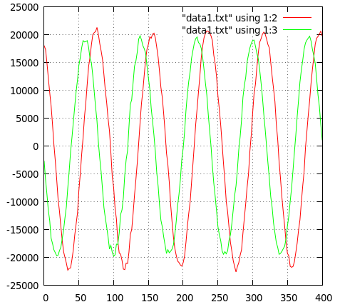
The IQ signals from Soft66LC4 is not saturated this time with the RF signal at LO+600Hz.
The DC is now at the center of the waterfall indicated by a thin red line. Since the IQ signals are inverted (actually they are QI instead of IQ), positive frequencies are plotted on the left half of the display. The bright red line is the actual RF signal, and the yellow line on the right half is its image.
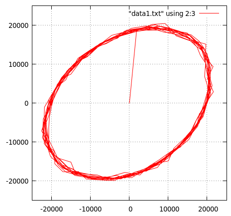
The gains for the IQ channels differs slightly.
And the phase difference for the IQ signals is not 90 degrees as you can see.
If we receive an RF signal which is 600Hz higher than that of LO, ideally we should have IQ signals which are cos(600Hz) and sin(600Hz), respectively, with the same amplitude and exactly with 90 degrees phase difference.
Unfortunately, we have some errors in the circuit, and we will have some_gain*sin(600Hz+some_phase) as a Q signal. (Without loss of generality, we can assume that the I signal is always perfect for our current purposes.)
So the problem is how we can recover the Q signal with some_gain to be 1.0, and some_pahse to be 0. Since we usually do only linear operations, what we can do is limited to compute the linear combination of the obtained IQ signals, namely, Q_adjusted = C1 * I_obtained + C2 * Q_obtained, where we assume both C1 and C2 are the frequency independent constants.
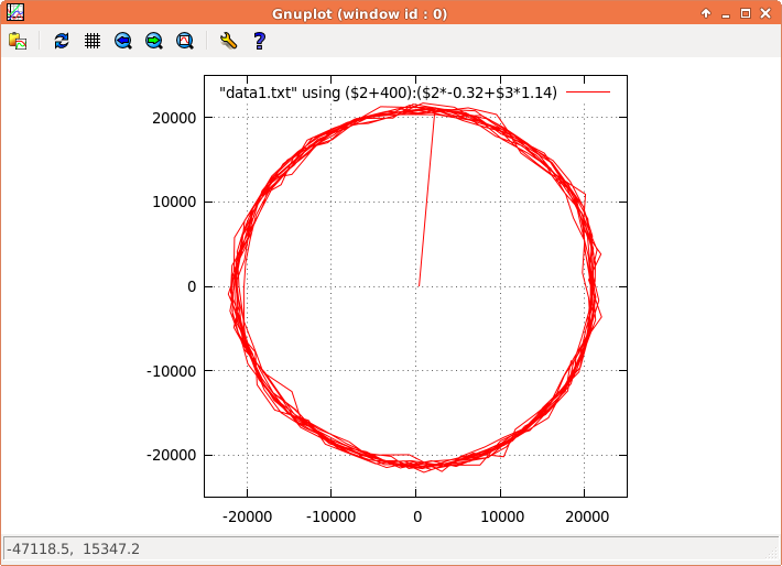
In our previous example, if we set, by observations, C1 to be -0.32 and C2 to be 1.14, and if we give DC offset of +400 to the I channel, we will get a nice circle as is shown below.
If you want to be more theoretical, you can fiddle with the equations such as (I’,Q’)=matrix([1,0], [a,b]) (I,Q), and (I,Q)=matrix([1,0],[-a/b, 1/b])(I’,Q’), etc., but the conclusion is the same.
    if(channels == 2) {
      for(int i =0; i < NFFT; i+=2) {
    	  audio_signal[i]   = samples[i] + 400.0;
    	  audio_signal[i+1] = -0.32*samples[i] + 1.14*samples[i+1];
      }
    }
With the above code, the image at -600Hz, which is on the right half of the display due to the inverted IQ signals, is much more suppressed.


