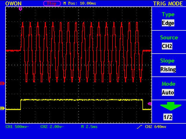
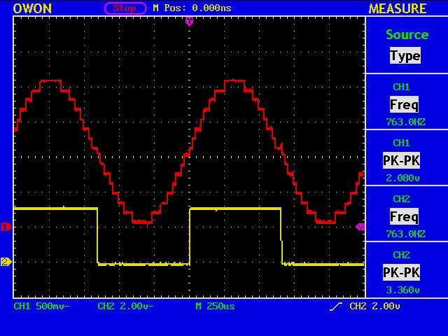
A four element D/A converter is used for generating a sidetone signal. The yellow trace shows the key output, now sending a dot. Note that the phase of the sinusoid is nicely aligned with the key output.
I wrote a short C program to obtain a sine table.
int main(){
	int n=64;
	char buf[16], buf2[16];
	for(int i=0;i<n;i++) {
		int ival = (sin((double)i/(double)n*360.0/360.0*2.0*3.14159265)+1.0)/2.0*15.0+0.5;
		itoa(i,buf,2,6);
		itoa(ival,buf2,2,4);
		printf("6'b%6s: begin WAVE <= 4'b%4s; end // %2d: %2d \n", buf, buf2, i, ival);
	}
	return 0;
}
The printed lines are like this and can be included into a verilog source file.
6'b000000: begin WAVE <= 4'b1000; end //  0:  8
6'b000001: begin WAVE <= 4'b1000; end //  1:  8
6'b000010: begin WAVE <= 4'b1001; end //  2:  9
6'b000011: begin WAVE <= 4'b1010; end //  3: 10
//
6'b111111: begin WAVE <= 4'b0111; end // 63:  7
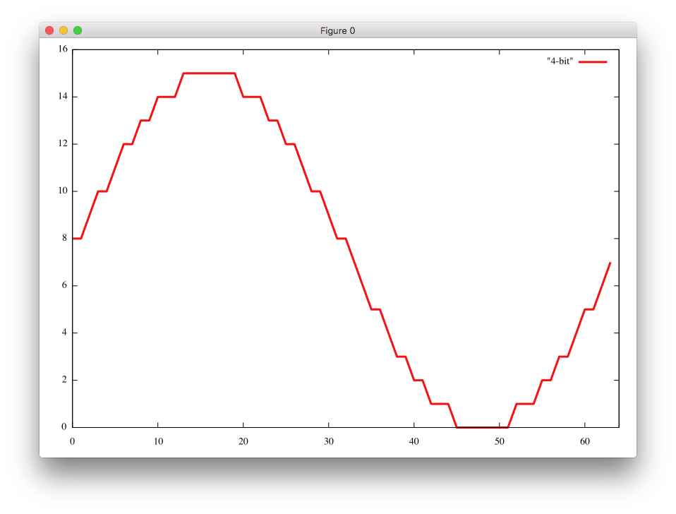
The interval [0 deg, 360 deg] is divided into 64 sections to utilise all the available output levels of a 4-bit converter.
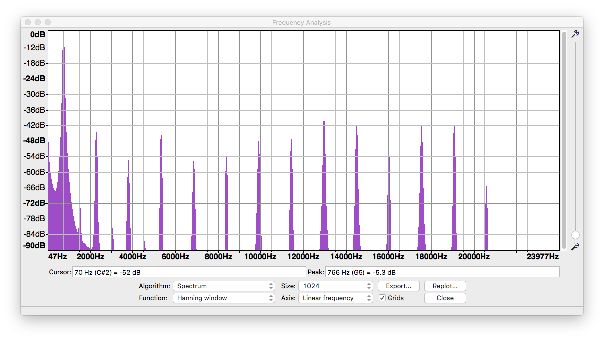
The sidetone signal is analog captured and analysed with FFT.