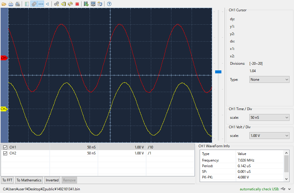
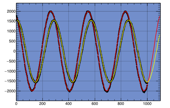
Now let’s try to measure the impedance of my dipole antenna. The figure shows the reference signal in red and the signal across the antenna in yellow. If the impedance of the dipole antenna is exactly 50 ohm, the two signals should be the same.
% head -15 owondata.txt
Save Time: 2016-09-11 13:27:26
Units:(mV)
                           CH1            CH2
Frequency:           7.026 MHz      7.042 MHz
Period:               0.142 uS       0.142 uS
SP:                   0.001 uS       0.001 uS
PK-PK:                 4.080 V        3.200 V

1              0.000                  1760.00        1560.00
2              0.001                  1760.00        1560.00
3              0.001                  1720.00        1560.00
4              0.002                  1720.00        1560.00
A text file obtained from the oscilloscope, OWON PDS 5022S, is fed into an AWK one-liner before being processed by a program written in ROOT.
% cat owondata.txt | awk 'NR>8 {print $1, $3}' >owondata_ch1.txt
% cat owondata.txt | awk 'NR>8 {print $1, $4}' >owondata_ch2.txt
// file name = mytest5.cc
{
  TGraph *g = new TGraph("owondata_ch1.dat");
  g->SetMarkerStyle( 20 );
  g->SetMarkerSize( 0.5 );
  g->Draw("AP");
  TF1 *f1 = new TF1("f1", "[0]*sin([1]*x+[2])+[3]");
  f1->SetParameter(0, 2000.0);
  f1->SetParameter(1, 0.022);
  f1->SetParameter(2, 0.0);
  f1->SetParameter(3, 0.0);
  f1->SetLineColor(kRed);
  g->Fit(f1);

  TGraph *h = new TGraph("owondata_ch2.dat");
  h->SetMarkerStyle( 24 );
  h->SetMarkerSize( 0.5 );
  h->Draw("P");
  TF1 *f2 = new TF1("f2", "[0]*sin([1]*x+[2])+[3]");
  f2->SetParameter(0, 2000.0);
  f2->SetParameter(1, 0.022);
  f2->SetParameter(2, 0.0);
  f2->SetParameter(3, 0.0);
  f2->SetLineColor(kYellow);
  h->Fit(f2);
}
% root mytest5.cc

****************************************
Minimizer is Minuit / Migrad
Chi2                      =       536853
NDf                       =          996
Edm                       =  7.63442e-09
NCalls                    =          148
p0                        =      2001.67   +/-   1.04511
p1                        =    0.0220756   +/-   1.82267e-06
p2                        =      2.03624   +/-   0.00102561
p3                        =     -12.2567   +/-   0.749788

****************************************
Minimizer is Minuit / Migrad
Chi2                      =       459226
NDf                       =          996
Edm                       =  8.91283e-08
NCalls                    =          128
p0                        =      1558.13   +/-   0.960465
p1                        =    0.0220847   +/-   2.15852e-06
p2                        =      1.50439   +/-   0.00124773
p3                        =     -14.2113   +/-   0.68435
The parameters p0 and p2 are the amplitude and the phase, respectively, so the amplitude ratio is 1558.13/2001.67=0.778415, and the phase difference is 1.50439-2.03624=-0.531850[rad]=-30.4728[deg].


