
Using the same elements and a cable, a 18MHz dipole is moved slightly in its position.
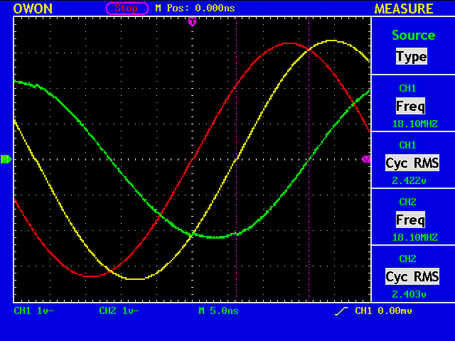
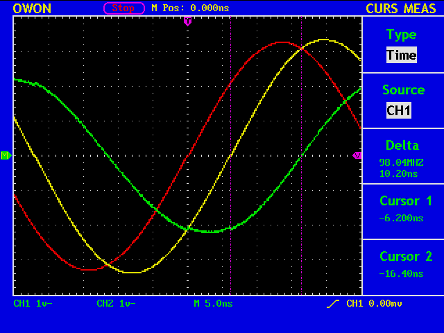
The voltage ratio V2/V1=2.403/2.422=0.992, and the delay of V2 against V1 is 40.4deg (=360deg*6.20nS/55.2nS).
(%i) V1:1.0+%i*0.0;
(%i) t:2.0*3.1416*(-40.4/360.0);
(%i) V2:0.992*(cos(t)+%i*sin(t));
(%i) Vr:2*V1-V2;
(%i) z:50.0*V2/Vr;
(%i) realpart(z);
(%o) 13.42379132002304
(%i) imagpart(z);
(%o) -32.76468187626101
(%i) abs(z);
(%o) 35.40794475617177
(%i) g:(z-50)/(z+50);
(%i) abs(g);
(%o) 0.6878765282155
(%i) SWR:(1+abs(g))/(1-abs(g));
(%o) 5.407720600329899
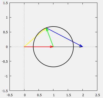
gnuplot> set object 1 rectangle from screen 0,0 to screen 1,1 fillcolor rgb "#f0f0f0" behind
gnuplot> set size square
gnuplot> set xrange[-0.5:2.5]
gnuplot> set yrange[-1.5:1.5]
gnuplot> set zeroaxis
gnuplot> set parametric
gnuplot> plot [0:2*pi] 1+cos(t)*0.6878,sin(t)*0.6878 lw 2 lt -1 notitle
gnuplot> set arrow 3 from 0,0 to 0.992*cos(40.4/360.0*2.0*3.1416),0.992*sin(40.4/360.0*2.0*3.1416) lw 2 lt 6
The same antenna, but at 7026kHz.
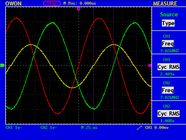
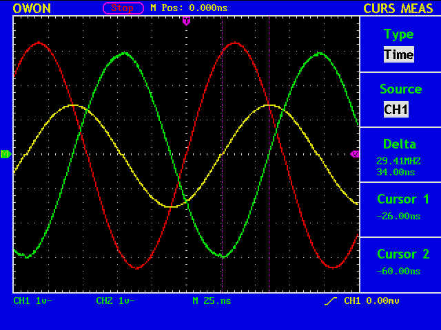
The voltage ratio V2/V1=1.008/2.409=0.418, and the delay of V2 against V1 is 65.8deg (=360deg*26.0nS/142.3nS).
(%i) V1:1.0+%i*0.0;
(%i) t:2.0*3.1416*(-65.8/360.0);
(%i) V2:0.418*(cos(t)+%i*sin(t));
(%i) Vr:2*V1-V2;
(%i) z:50.0*V2/Vr;
(%i) realpart(z);
(%o) 2.40689877387539
(%i) imagpart(z);
(%o) -10.92662280617141
(%i) abs(z);
(%o) 11.18857665907635
(%i) g:(z-50)/(z+50);
(%i) abs(g);
(%o) 0.91215699937376
(%i) SWR:(1+abs(g))/(1-abs(g));
(%o) 21.76789255537643