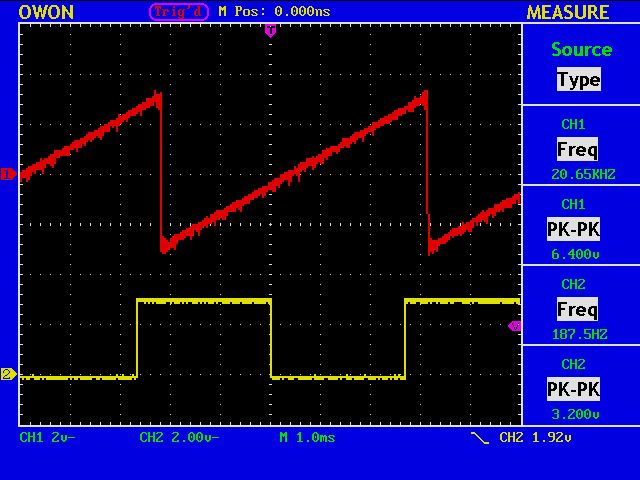
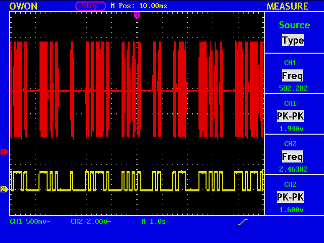
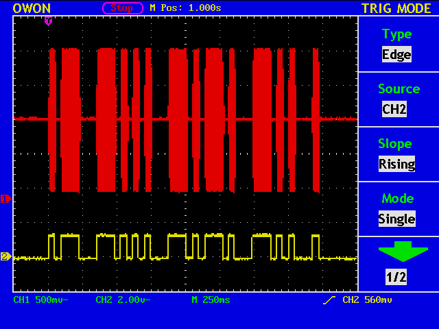
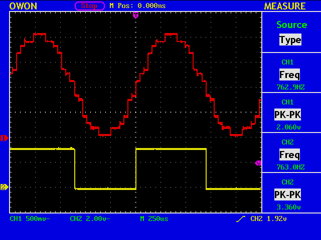
O.K. It works. The value of an 8-bit counter and 24 zeros are fed into a dac with Fs = 48kHz. (Note that 48kHz divided by 256 makes 187.5Hz.)
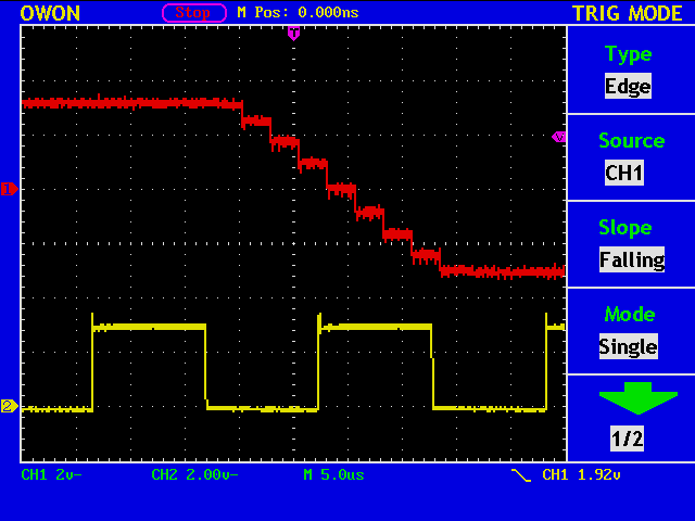
This figure shows that the dac has a eight times oversampling FIR interpolation filter.

Ham Radio Blog
O.K. It works. The value of an 8-bit counter and 24 zeros are fed into a dac with Fs = 48kHz. (Note that 48kHz divided by 256 makes 187.5Hz.)
This figure shows that the dac has a eight times oversampling FIR interpolation filter.
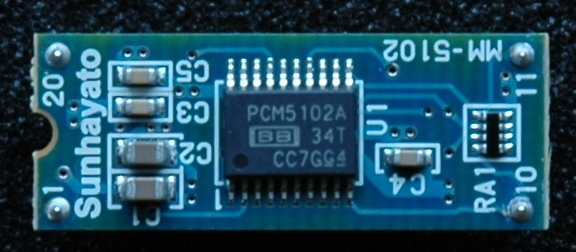
This is a d/a converter module using TI’s PCM5102A.
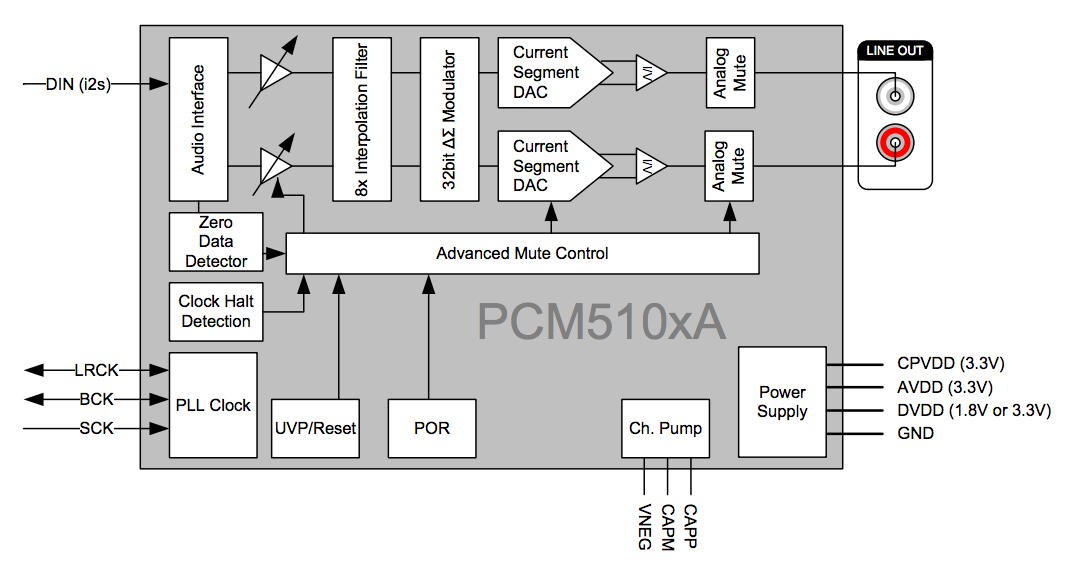
The chip can accept 16-, 24-, and 32-bit data, and should perform much better than my homebrew 4-bit dac.
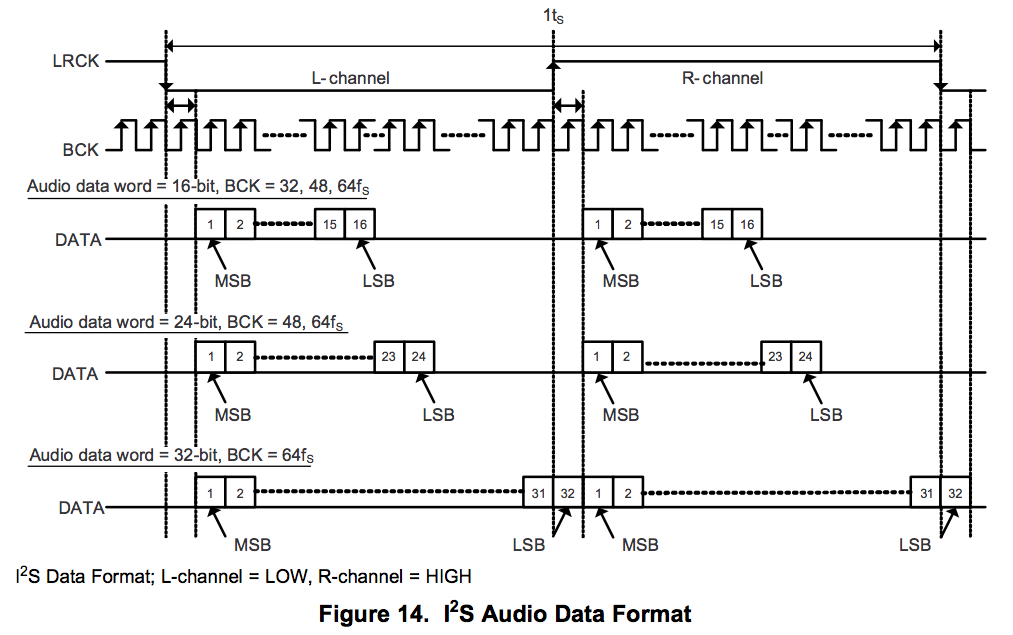
The interface is I2S, and should easily implemented in a FPGA.
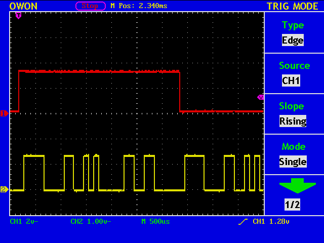
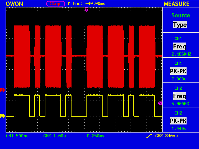
The waveforms show LRCK and DATA. A fixed 32-bit pattern of 32’b1111_0000_1100_1010_0000_1100_1100_0000 is continually sent for both L and R channels.
A Morse code table must be included in an FPGA to receive a message and generate a key output signal that corresponds to the text.
Oops! The code “G” is missing.
There are various kinds of pulse shaping filters, but since we are dealing with sidetone, the purpose of which is to serve as feedback to the operator manipulating his/her paddle, the shape of the filter, and hence the resulting sound, should be determined solely by the aesthetic sense of each person.
This makes the problem extremely difficult in a sense, because there is no way to determine the best.
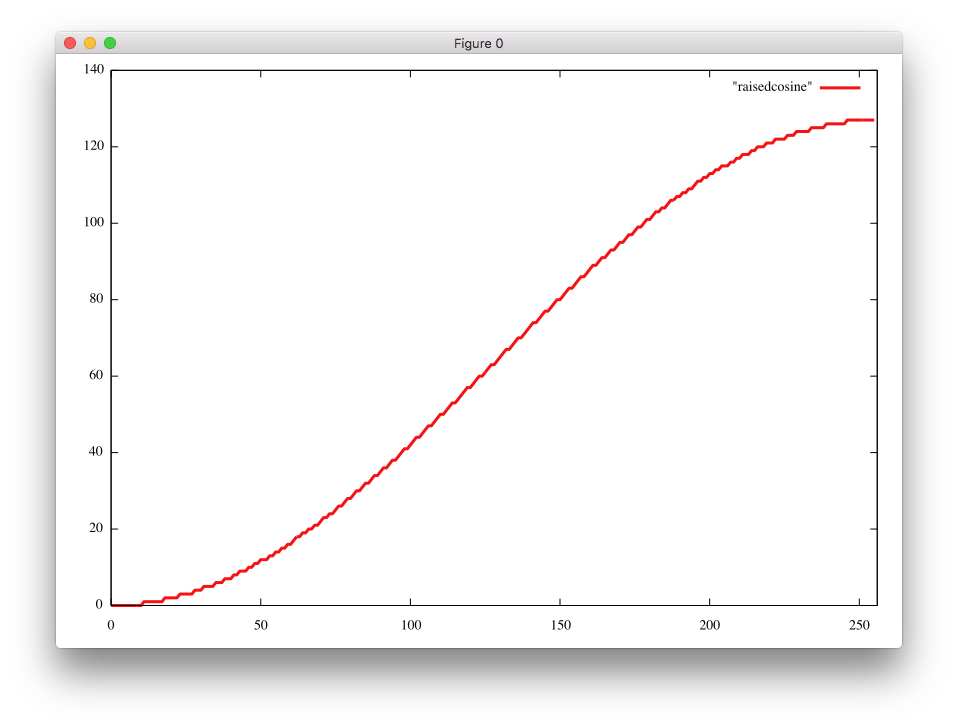
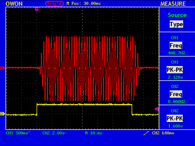
One candidate is a raised cosine shape. The shape, used in a frequency domain, is very popular in the field of digital communications, because it can limit the bandwidth of the signal without introducing Intersymbol Interference (ISI).
Does the envelope look like a raised cosine?
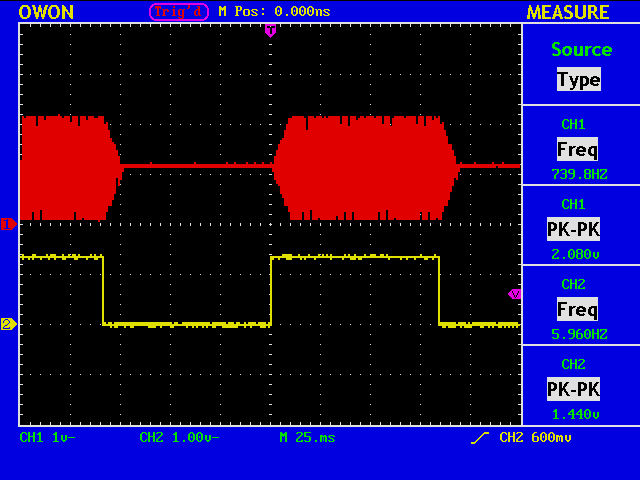
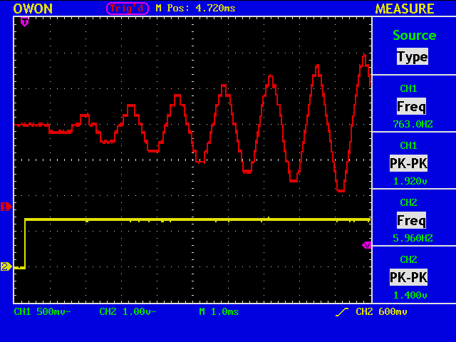
Sinusoidal sidetone with controlled envelope is generated in an FPGA. The parameters could be rise and fall times if the envelope changes linearly, and others for other window functions.
Now trying to have a Morse code table.
    always @ (send_char) begin
        case(send_char)
            5'b00000: begin morse_code <= 16'b1011_1000_0000_0110; end
            5'b00001: begin morse_code <= 16'b1110_1010_1000_1010; end
            5'b00010: begin morse_code <= 16'b1110_1011_1010_1100; end
            5'b00011: begin morse_code <= 16'b1110_1010_0000_1000; end
            5'b00100: begin morse_code <= 16'b1000_0000_0000_1100; end
//
The four LSBs are used to indicate the code length. I do not feel a strong need for such features as adjustable weighting, adjustable dot/dash ratio, etc., so this rather primitive format will do.
Sending an internally stored message.
    always @ (message_state) begin
        case(message_state)
            5'b00000: begin message_text <= 16'b1110_1011_1010_0011; end
            5'b00001: begin message_text <= 16'b1011_1010_1110_0000; end
//
        endcase
    end
The pattern for the key output signal is directly encoded in 16-bit words.
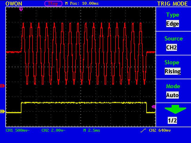
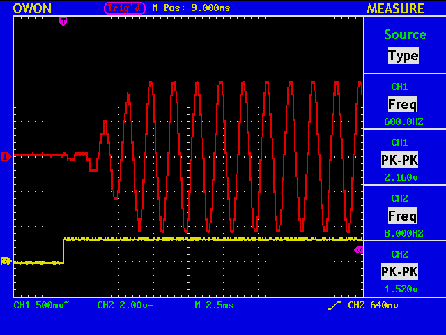
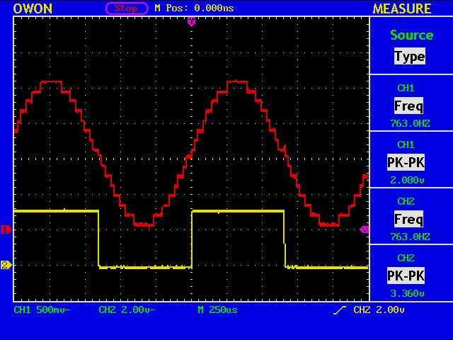
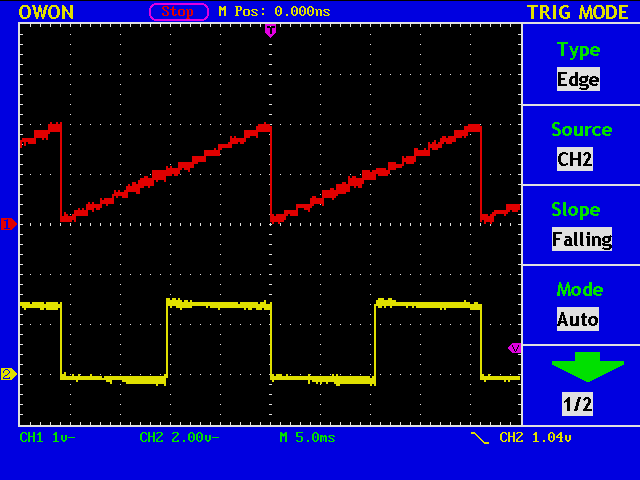
A four element D/A converter is used for generating a sidetone signal. The yellow trace shows the key output, now sending a dot. Note that the phase of the sinusoid is nicely aligned with the key output.
I wrote a short C program to obtain a sine table.
int main(){
	int n=64;
	char buf[16], buf2[16];
	for(int i=0;i<n;i++) {
		int ival = (sin((double)i/(double)n*360.0/360.0*2.0*3.14159265)+1.0)/2.0*15.0+0.5;
		itoa(i,buf,2,6);
		itoa(ival,buf2,2,4);
		printf("6'b%6s: begin WAVE <= 4'b%4s; end // %2d: %2d \n", buf, buf2, i, ival);
	}
	return 0;
}
The printed lines are like this and can be included into a verilog source file.
6'b000000: begin WAVE <= 4'b1000; end //  0:  8
6'b000001: begin WAVE <= 4'b1000; end //  1:  8
6'b000010: begin WAVE <= 4'b1001; end //  2:  9
6'b000011: begin WAVE <= 4'b1010; end //  3: 10
//
6'b111111: begin WAVE <= 4'b0111; end // 63:  7
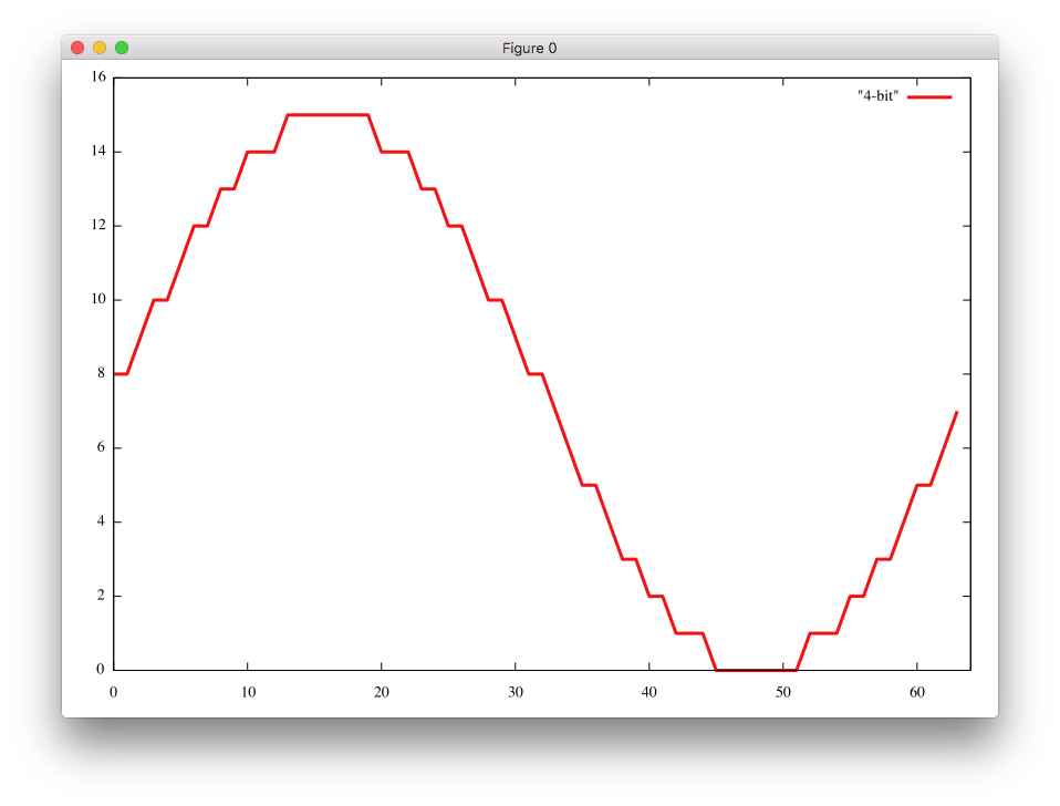
The interval [0 deg, 360 deg] is divided into 64 sections to utilise all the available output levels of a 4-bit converter.
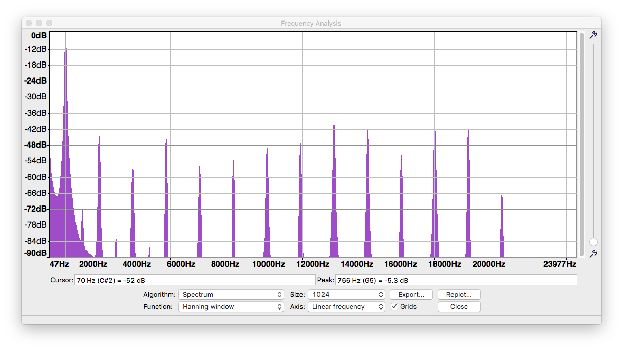
The sidetone signal is analog captured and analysed with FFT.
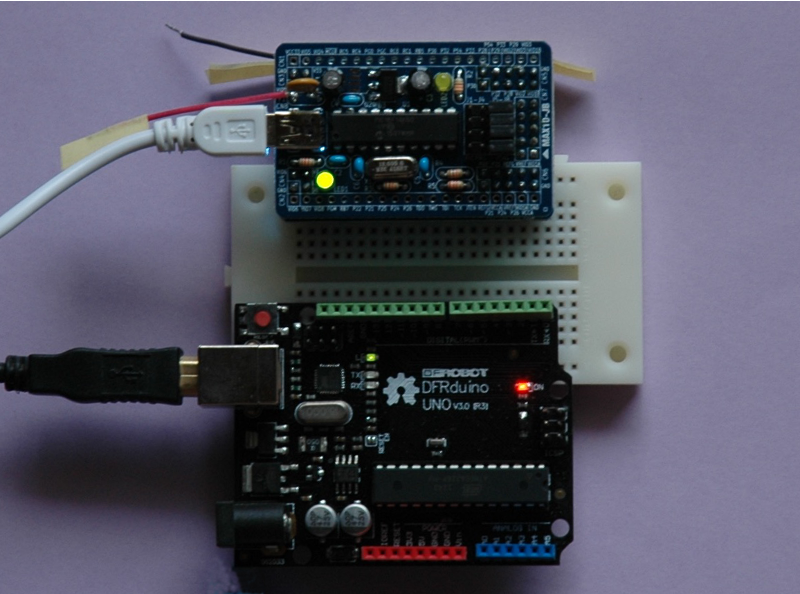
If you only have a single transceiver, it may not be very convenient in doing experiments. A separate transmitter and a receiver will do much better.
So here is my separate system. The Arduino board is going to work as a pulse pattern generator to debug the FPGA board.
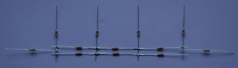
Not a beam antenna, but a D/A converter of a R-2R ladder type.
https://en.wikipedia.org/wiki/Resistor_ladder
The waveform looks like a sine wave?
Monotonicity is OK.