Resonant Antennas (2)

You said "Z=73.13+j*42.55+j*We*k*delta", but, actually the real part of Z (=73.13) is also a function of delta, right?

Yes, it’s an approximation considering that the change of the real part is relatively small compared with that of the imaginary part.

O.K. We assume that. And under that assumption, can you say that we get the best (=minimum) VSWR value if the antenna is in resonance?

That is a good question, which I can answer using a Smith Chart, but before doing that, you must remember that VSWR=(1+rho)/(1-rho), where rho is the absolute value of the reflection coefficient, gamma. And that it is a monotonically increasing function of rho, which means VSWR becomes minimum when rho is minimum.

capture_001_22102013_174743

Resonant Antennas

capture_001_21102013_225545

An antenna is said to be resonant if its input impedance (or feed point impedance), Z=R+jX, is purely resistive, which means its reactance X is exactly zero.

The input impedance of a half-wave dipole is approximated by the equation:

Z=73.13+j*42.55+j*We*k*delta,

where We and k are some constants, and delta is the excess length of an antenna over half the wavelength. Since both We and k are positive, we can make X to be zero by shortening the element slightly, usually a few percent depending on the diameter of the element.

The question here is what is the physical and practical meaning of the antenna being in resonant.

capture_003_21102013_225756

References:
[1] “Antenna and Radio propagation (in Japanese)” by Yasuto Mushiake,
[2] MMANA-GAL basic.

Scattering from a receiving antenna

capture_001_20102013_204847

capture_003_20102013_210652

The above two figures are from
Mats Gustafsson et al., Forward scattering of loaded and unloaded antennas.

A receiving antenna interacts with an incoming electromagnetic wave. However, its interaction is not limited to absorption of the energy but includes some scattering from the antenna.

As is described in “Antenna and Radio propagation (in Japanese)” written by Yasuto Mushiake, pp 39-42, the scattering cross section of an (receiving) antenna loaded with Zl is given by

As= (R^2/abs(Z+Zl)^2)*4Ae,

where Z=R+jX is the input impedance and Ae is the effective area of the antenna.

The scattering cross section As is a function of Zl, and obviously As(max)=4Ae when Zl=0. And if Zl is selected to be Zconj=R-jX, then As=Ae, which means the antenna emits the same amount of power as it supplies to the receiver.

Which do you prefer?

smithg1circle6

We have two blue dots, which one should I use?

If you want to make the cable length to be minimum, you should definitely choose the closer one to the red point.

You mean closer when we go clockwise starting from the red point.

Correct.

What happens if I do not care for the cable length?

In that case, you can choose whichever you like. If you choose the blue dot on the upper half plane, the impedance Z there will be 50+jX [ohm], where X is some positive number.

smithg1circle7

Or if you choose the blue dot on the lower half plane, the impedance Z will be 50-jX [ohm], where X is the same as before.

Which means?

Which means, you put some capacitance in series in the former case, and some inductance in the latter case.

Device Under Test (2)

cursor2

Now, let’s try again with another DUT.

cursor1

This time there is a phase difference, so we must determine complex impedance in the form Z = R + jX.

cursor

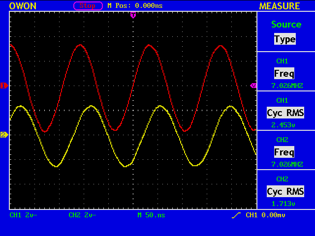
The voltage ratio is: V2/V1 = 1.713 [v] / 2.453 [v] = 0.698, and the phase difference is: 360.0 [deg] * (-22.80 [nS] / 142.32 [nS]) = -57.7 [deg], where 142.32 [nS] is the period for 7026kHz.

Assuming you know the answer that the DUT is 100 [ohm] // 1 [nF], the voltage ratio and the phase are obtained in the following manner. (This is a reverse way.)

(%i1) r6:50;
(%i2) r:100;                      <- here is your 100 [ohm]
(%i3) x:1/(%i*2*%pi*7026e3*1e-9); <- here is your 1 [nF]
(%i4) z:r*x/(r+x);
(%i5) v2:z/(z+r6);
(%i6) float(2*abs(v2));
(%o6) 0.74942127142784            <- voltage ratio
(%i7) float(carg(v2)*360/(2*%pi));
(%o7) -55.80120705365476          <- phase difference

In most cases you do not the answer in advance, so you must go like this:

(%i1) t:(-57.7/360.0)*2.0*3.16; <- measured phase difference
(%i2) v:0.698/2.0;              <- measured voltage ratio
(%i3) r:50.0;
(%i4) float(solve([(R*(r+R)+X^2)/((r+R)^2+X^2)=v*cos(t),r*X/((r+R)^2+X^2)=v*sin(t)],[R,X]));
(%o4) [[R=-50.0,X=0.0],[R=4.183382859001799,X=-19.67880950916058]]
(%i5) Z:4.1833-19.6788*%i;
(%i6) Y:1/Z;
(%i7) 1/realpart(Y);
(%o7) 96.75499446131043         <- Real part of Z (nominal 100 [ohm])
(%i8) 1/imagpart(Y);
(%o8) 20.56808181037462         <- Imaginary part of Z
(%i9) C:1/(2.0*3.1416*7026e3*1/imagpart(Y)); <- convert to capacitance
(%o9) 1.1013292647891441*10^-9  <- 1.1 [nF] (nomnal 1 [nF])

To verify the above result, we go again the reverse way:

(%i1) r6:50;
(%i2) r:96.755;                        <- R=96.755 [ohm]
(%i3) x:1/(%i*2*%pi*7026e3*1.1013e-9); <- C=1.1013 [nF]
(%i4) z:r*x/(r+x);
(%i5) v2:z/(z+r6);
(%i6) float(2*abs(v2));
(%o6) 0.69801459091613                <- voltage ratio
(%i7) float(carg(v2)*360/(2*%pi));
(%o7) -58.03754068937465              <- phase difference

Not bad?

Device Under Test

attbridge

With a signal generator (SG), you can make a measurement of various parameters of your device. One example is impedance measurement.

bridge

A fixed attenuator is inserted in front to improve the souce match. For 6dB attenuation, use R1=39 [ohm], R2=R3=150 [ohm]. “X” is the device under test (DUT), and R4=R5=R6=50 [ohm]. In the photograph, a 100 [ohm] resistor is employed as a DUT.

dut100ohm

IC-7410 with tx frequency 7026kHz is used as a SG. RF power is minimized to 2 [W]. CH1 (in red) shows “V1”, and CH2 (in yellow) shows “V2”.

xy

Since the DUT, a 100 [ohm] resistor, is pure resistive, there is no phase difference between the two waveforms.

solve

By solving a simple equation, we conclude that the impedance of our DUT is 94.6 + j*0 [ohm].