

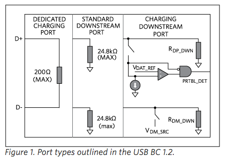
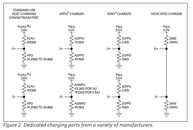
Receiving DC power (+5V) via USB I/F is somewhat complicated due to various standard and custom protocols employed. Sometimes D+ and D- lines are used to convey information.
https://www.maximintegrated.com/en/app-notes/index.mvp/id/5801
http://www.ti.com/lit/ds/symlink/tps2540a.pdf
This causes a problem with the PIC board, MAX10-JB, because some of the I/O pins of the PIC microcontroller are used both for D+ and D- lines for USB I/F, and for writing into its flash program memory.
To avoid interference, I pulled off the USB cable and used an external power supply just while programming the flash memory.
The green flushing LED on the FPGA evaluation board, MAX10-FB, shows that the flash memory was successfully programmed and the verification was OK.