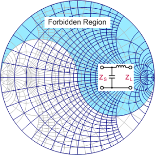
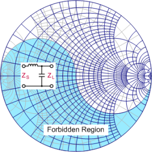
Now let’s take an example to see how there exits a forbidden region for a given type of network.
http://www.amanogawa.com/archive/LMatch/LMatch-2.html
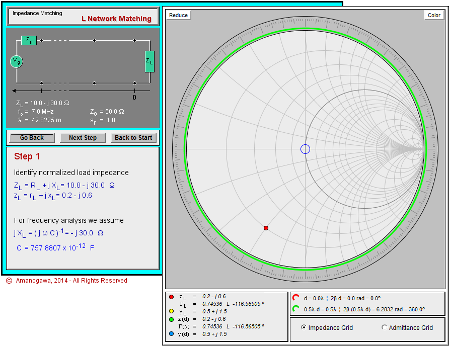
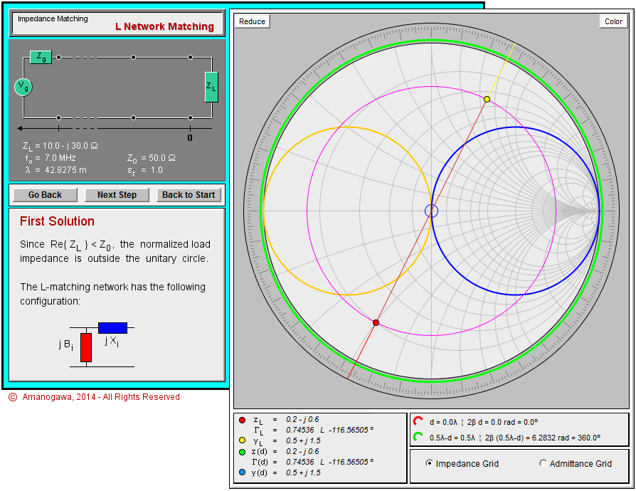
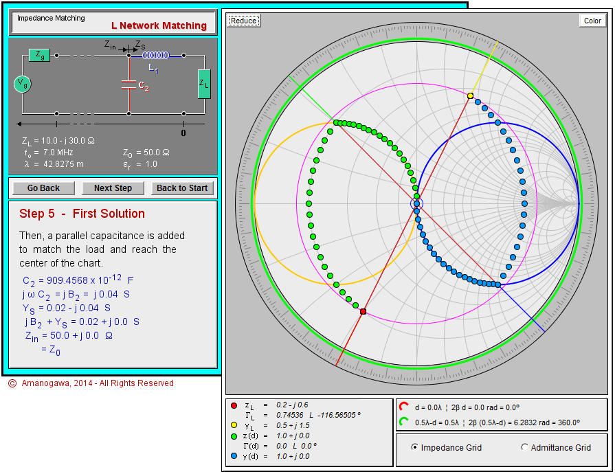
Suppose you antenna has the load impedance of ZL=10.0-j30.0 [ohm] (red dot). Note that ZL does NOT fall onto the forbidden region of the L-section network of the type mentioned in the first figure, so it can somehow be matched to the system impedance of Z0=50 [ohm].
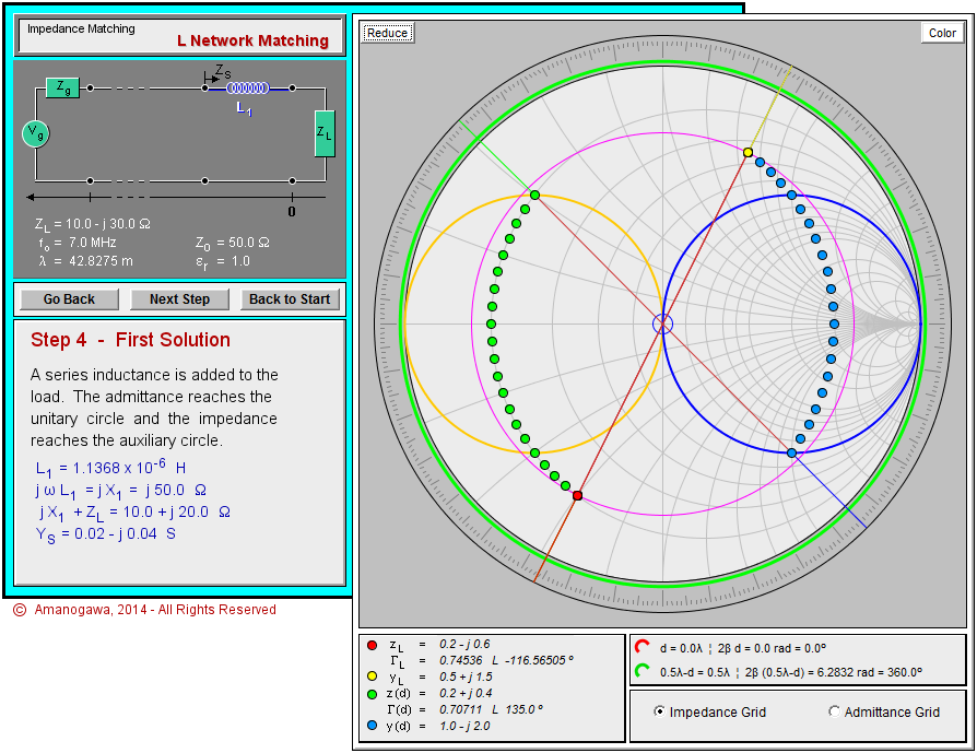
Since you first add some inductance XL (blue box) to ZL in series, and then some capacitance XC (red box) in parallel, the combined XL+ZL must lie on upper half of the constant g=1 circle (yellow circle) on the Smith Chart.
This is because adding a capacitor in parallel means a clockwise movement on a constant g circle, and because your destination is the center of the Smith Chart, namely Z0=50 [ohm]. If you start somewhere from the lower half of the yellow circle, you must use an inductor instead of a capacitor to reach Z0, but this is going to be another story which we are not talking about right now.
So in summary, XL (blue box) moves your ZL (red dot) onto the place on the upper half of the yellow circle (see the green dots for the locus),
and then you use XC (red box) to finally goes on to Z0. (Never mind the yellow dot and the blue dots. The same things can be said both in terms of impedance (Z) and admittance (Y), where Y=1/Z.)
Starting from any ZL (red dot) NOT in the forbidden region, you can always reach Z0 as long as you have an inductor and a capacitor with the appropriate values.
In other words, the forbidden region in this particular type of the network is the area where you can not reach the upper half of the g=1 circle (yellow circle) by adding an inductor in series to ZL (red dot).

