Since I am a CW lover, and CW having the great virtue of constant envelope and being a nice friend of class-C amplifiers, IMD measurements had never been of my interest…
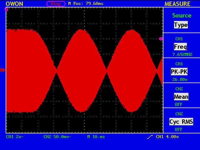
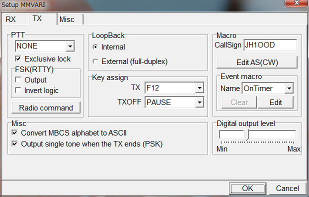
O.K. This is a PSK31 signal in radio frequency. The baseband signal is generated by MMVARI with its digital output level slider adjusted to have no significant clipping. The signal is fed to IC-7410 through its USB I/F with “USB Mod Level (menu 39)” set to 25%.
Sometimes it is more flexible to use a signal generator program to obtain PSK31 like signals.
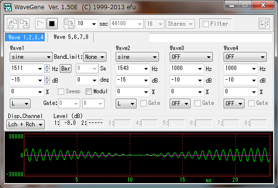
This signal is also fed to IC-7410 using the same USB I/F, and what you will obtain is:
Looks almost the same?
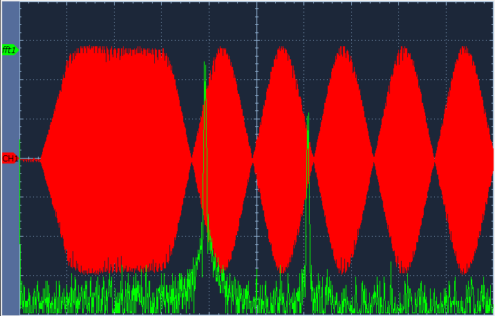
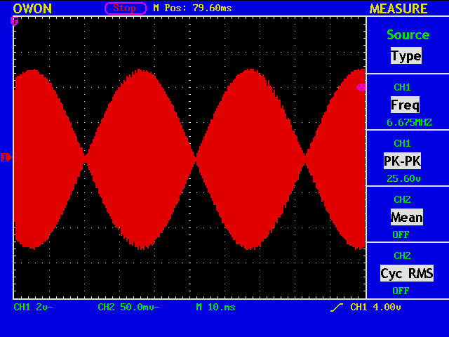
Now to measure the two-tone third order IMD of your transmitter or transmission system including the baseband part, you usually use a spectrum analyzer, but since I do not have one (not currently, I mean), I must be satisfied with analyzing the audio signals converted from RF signals by a receiver, perhaps with a Direct Conversion Receiver, Soft66LC4.
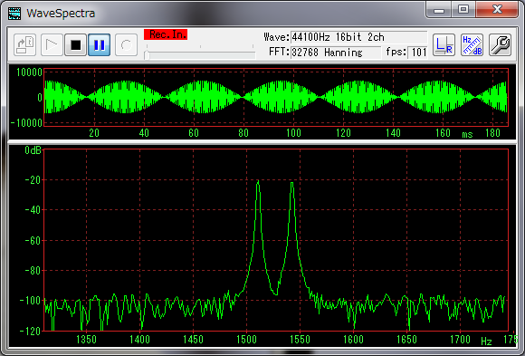
This is not a received audio signal, but a loopback audio signal, or monitor out signal, from IC-7410.
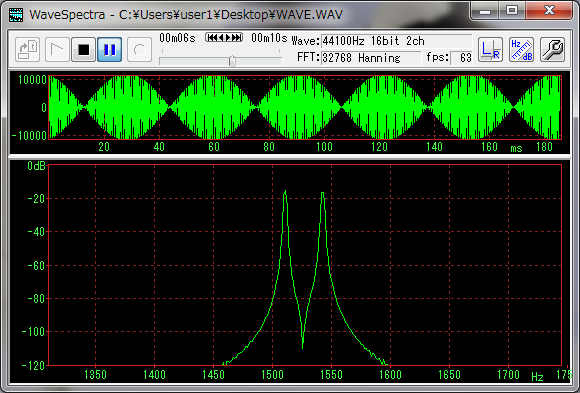
This is the original signal generated by WaveGene. The difference is due to the various level adjustment scheme in the “Windows Audio Architecture” and the internal processing of IC-7410.