Bent Dipole with a short Parallel Transmission Line

bentDipole

This is my antenna with a home-brew parallel transmission line between the feed point and the ATU, ICOM AH-4.

Over the weekend I tried the antenna on the 40m/30m/20m/15m/10m/6m bands mostly with domestic stations. It also works on the 17m/12m bands, but I could not have a QSO in a short time available for me.

Table Top Equipment Rack (2)

cutout

AUTODESK 123D Design is an intuitive type of software, so you may need some tricks to exactly obtain what you have in your mind. Here I am using snap operations and “A not B” Boolean operations.

cutout2

Now here is a rack (350mm x 350mm x 410mm) I designed.

desk

It should look like this on my desk.

Table Top Equipment Rack

beforeRack

I thought I needed an equipment rack on my desk.

capture_001_18082014_221229

First some simulations with AUTODESK 123D Design.

My two (yes, I only have two.) paddles go under the shelf and sit on the table, then in the middle the space for IC-7410, and on the top shelf, the power supply unit and the power/SWR meter. The speaker may go on top of the rack.

Antenna and 300 ohm feeder (2)

Zls50b

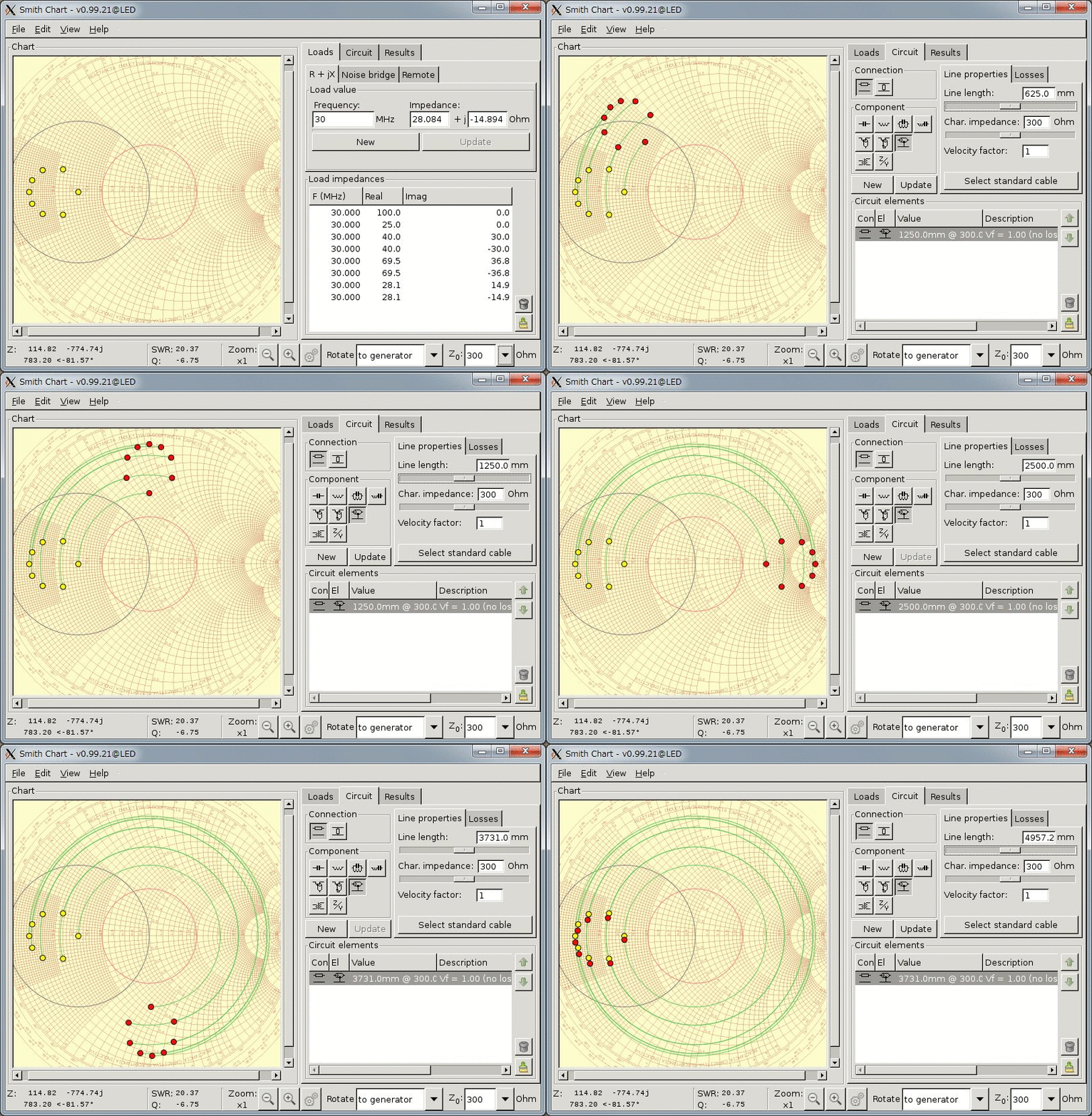
The loci (grenn circles) of Zin (red dots) may look weird, but this is only due to the fact that the system impedance of the Smith Chart here is set to 50 [ohm] and not to the characteristic impedance of the transmission line, which is 300 [ohm] in this case.

in300ohm

If you draw the same chart with the system impedance of 300 [ohm], you will now obtain the concentric circles, which you often see on a Smith Chart.

Note that the ZLs (yellow dots), which gives a VSWR value of 2 in a 50 [ohm] system, are much less than 300 [ohm], and now they appear on the left part of the chart.

Antenna and 300 ohm feeder

concentric300ohm

So what happens if you use a, say, 300 ohm feeder cable for your antenna.

First, We need to assume the feed point impedance, ZL, of the antenna. Let’s say the VSWR of the antenna when used with a coaxial cable is around 2, which means the absolute value of the reflection coefficient, abs(gamma), is 1/3 (red circle).

VSWR=(1+abs(gamma))/(1-abs(gamma))
abs(gamma)=(VSWR-1)/(VSWR+1)

Since the VSWR value tells you nothing about the phase of gamma, we assume 8 points (yellow dots) equispaced on the red circle.

By varying the cable length, the input impedance (red dots), Zin, observed at the near end of the cable, changes as is shown in the figure.

Appendix: How to get equispaced ZLs on a constant VSWR circle. Here VSWR is assumed to be 2, and therefore abs(gamma) to be 1/3. The code is in pseud-maxima.

z(g):=(1+g)/(1-g);
g(t):=(1/3)*(cos(t)+%i*sin(t));
t(n):=n*2.0*%pi/8.0;
n:1
50.0*float(realpart(z(g(t(n)))));
50.0*float(imagpart(z(g(t(n)))));

Not concentric

concentric70

Where are the centers of these two green circles? Are they concentric?

Noting that the input impedance, Zin, of a quarter-wave line, the characteristic impedance of which being Z0, is given by Zin=Z0^2/ZL, and let ZL=1/2 or 2 (normalized to the system impedance of 50 [ohm]), and also let Z0=sqrt(2), then you will have Zin=4 or 1.

Therefore, the centers of the circles on a complex reflection coefficient (gamma or “g” in short) plane, or on a Smith Chart, are:

g(z):=(z-1)/(z+1);
(g(1)+g(2))/2=(0+1/3)/2=1/6=0.167
(g(1/2)+g(4))/2=(-1/3+3/5)/2=2/15=0.133

So the circles are NOT concentric because 1/6 and 2/15 differ each other.

concentric150

This is more evident in the case Z0=150 (or 3 if normalized). In this case, let ZL=1/2 or 2 again, then Zin=18 or 9/2, and the centers of the circles are:

(g(2)+g(9/2))/2=(1/3+7/11)/2=16/33=0.485
(g(1/2)+g(18))/2=(-1/3+17/19)/2=16/57=0.281

You can see easily that the two green circles are not concentric.

Transmission line as an impedance transformer (2)

if70ohm

Note: Please click the figure for the better results.

If the load impedance, ZL, is 100 [ohm] (the yellow dot on the right), Zin becomes 50 [ohm] by using a quarter-wave transmission line with the characteristic impedance Z0 = sqrt(ZL*Zin)=sqrt(100*50)=70.7 [ohm].

Transmission line as an impedance transformer

if50ohm

Note: Please click the figure for the better results.

A transmission line with the characteristic impedance, Z0, not equal to the load impedance, ZL, works as an impedance transformer. A most popular example is a quarter-wave impedance transformer. In this case, the electrical length of the line is exactly lambda/4, and the input impedance of the line Zin is given by the equation Zin=Z0^2/ZL

In the figure, there are two types of loads (yellow dots), ZL=100 [ohm] and ZL=25 [ohm]. Notice that input impedance (red dots) of the line becomes either Zin=50^2/100=25 [ohm] or Zin=50^2/25=100 [ohm], respectively, as the line length approaches quarter wavelength.

Home-brew parallel transmission line

feeder

Spacers are made of a plastic (Polyethylene Terephthalate, or PET) bottle. The line is between the feed point of my dipole and the automatic antenna tuner. The length of the line is about 1.5 meter, or 5 ft.

The characteristic impedance? Well, I do not know. Let’s say it is around 400 [ohm].

Cygwin/X

cygwin0

Cygwin/X is a port of the X Window System to the Cygwin, which provides a UNIX-like API layer for the Microsoft Windows.

I do not like to do everything on Cygwin, but just using an X server is acceptable for me.

cygwin

Here HP-dv6 is a UNIX machine to which an ssh connection with X11 forwarding is established.