Arduino Leonardo (8)

arduinoCW11

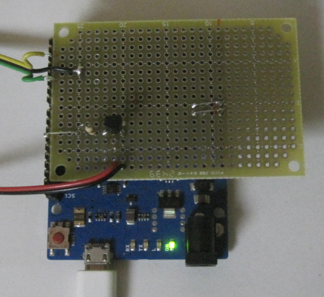
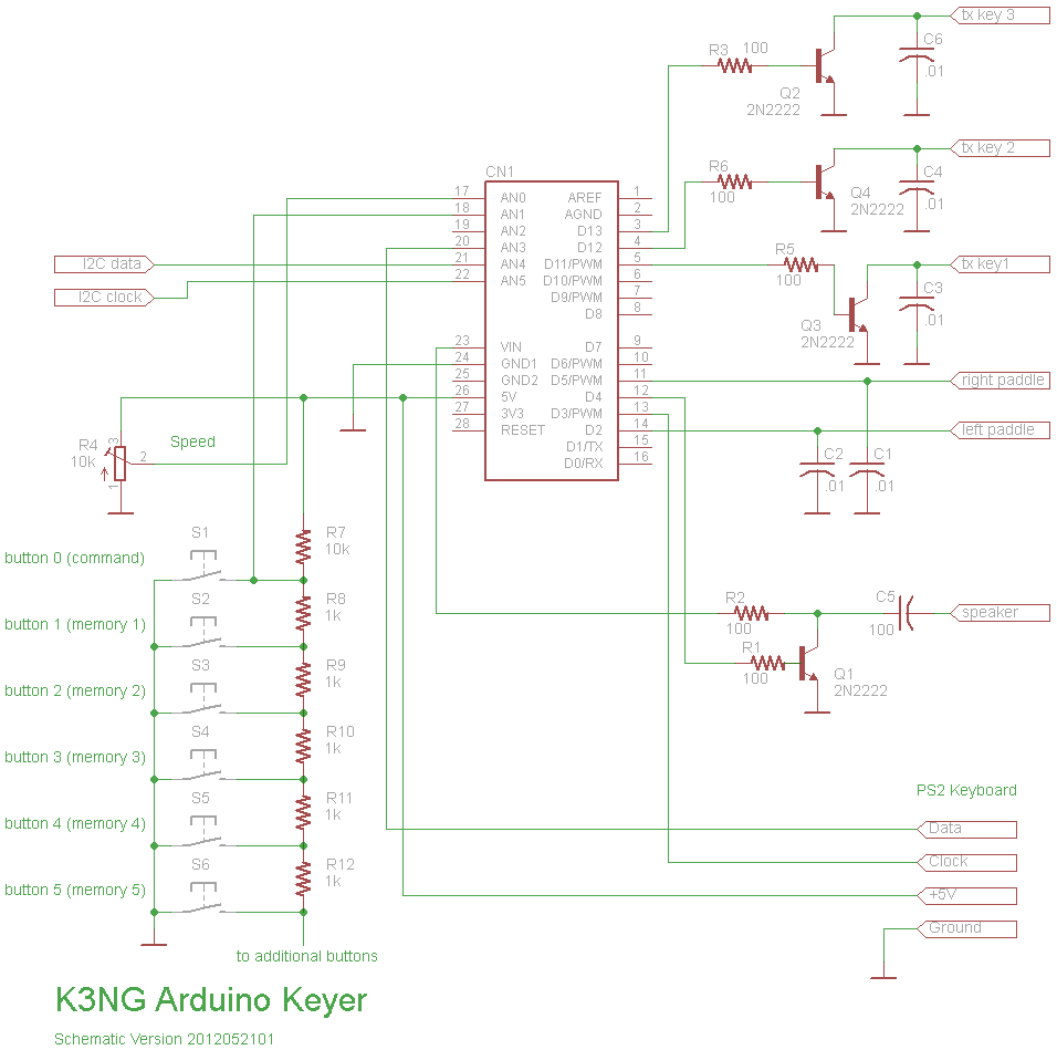
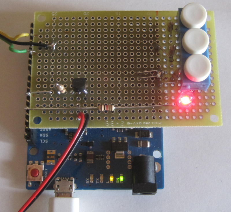
I added some buttons, a command button to enter into command mode, in which you can enter various commands from your paddle, and two buttons for memory messages.

The red LED shows you are currently in command mode.

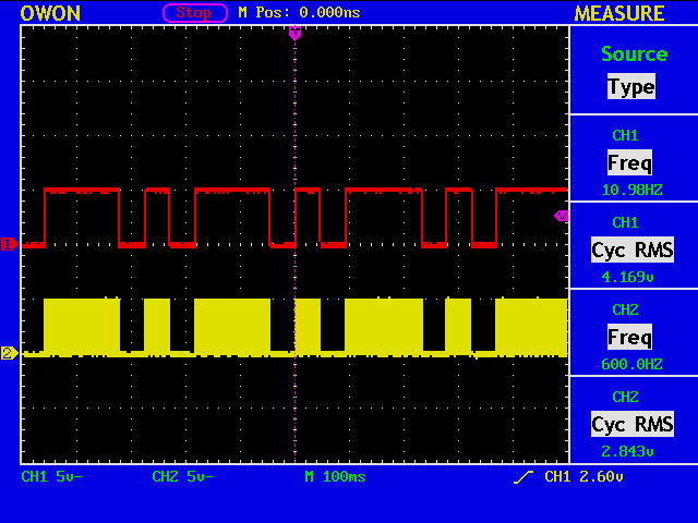
One thing I did not expect was that in command mode only the side-tone output is available to monitor your paddle manipulation. Right now, the square wave side-tone signal is ignored because I thought the tone from the rig is more agreeable.

Arduino Leonardo (7)

I checked the IC-7410 service manual, which you can find easily with Google, to see if I can connect the keyer output signal from ATmega32u4 used in an Arduino Leonard board directly to the ELE-KEY inputs of my rig. The input signals are named “DOTK” and “DASHK”, and if you trace the lines, you will find that the both signals go directly into the Front CPU (M30622F8PGP microcontroller), to which the Vcc of 3.3V is supplied.

Actually, the voltage at the ELE-KEY inputs is measured to be around 3.3V. Since the Vcc of ATmega32u4 on the Leonard board is 5V, we need to use either a level converter, most simply with two resistors, or an open collector (drain) circuit. It seems that the latter is the preferred choice, because it is a more generic approach.

Arduino Leonardo (6)

arduinoCW8

A small universal board is used to be plugged on top of the Arduino board. Such boards are called “shields” in Arduino terminology.

The red and black lines go to the rig (keyer output), and the yellow, green and black lines go to the paddle.

arduinoCW9

Since you have a full control over the keyer from your PC, there are no volumes nor switches on the “shield”.

arduinoCW10

Do not forget to uncomment the following line in “keyer_features_and_options.h”:

#define FEATURE_MEMORIES

to enable the memories feature.

Arduino Leonardo (5)

arduinoCW7a

The CW Keyer program by K3NG is very versatile, and if the Keyer is connceted to a PC with a USB cable, although it is not necessary to use the Keyer, you can issue a command or a message to be sent from the keyboard using any terminal emulator programs such as PuTTY.

Arduino Leonardo (4)

arduinoCW6

A keying output buffer (2SC1815) is used to connect the Aruduino CW keyer to my rig. The two lines (red) go to the rig, and the three lines (green) go to the paddle.

2SC1815

aruduinoCW4

The red trace is the keying output before inverted by the output buffer, and the yellow trace is the side-tone from the rig.

Arduino Leonardo (3)

arduinoCW3

I tried the CW keyer program by K3NG. The two blue lines connected to the probes are for Keying Output and Side-tone, respectively. The green line goes to the GND, and two blue lines go to my paddle.

arduinoCW2

These are the waveforms when the paddle is squeezed. The red trace shows the Keying Output, and the yellow one is the Side-tone around 600Hz.

Orpheus

orfp1514.zoom47

You may sometimes need an audio mixer to combine audio signals from your rig and from other equipment like your pc. This is Orpheus from Prism Sound, which I obtained when I was still an audio-freak.

Let’s see if I can play music from my PC…

capture_001_02032014_185722

This is a control panel of Orpheus. There are 8 analogue output channels.

orpheus

Seems and sounds OK!

Blog to Ebook Conversion (6)

Now you have a file that contains just one article, and you wish to extract three things out of each file, which are:

  • Title
  • Date
  • Text

Assume again that you find by inspection of the files that they are contained in the lines like this:

<h2><a href="...">Need to repare my rig</a></h2>
<div class="entry_text">When I switched on my rig this morning...</div>
<li>[2014/03/01 05:43]

A short awk program will do the job for you to convert the files into html format which can then be fed to Ebook authoring tools.