Stub in your shack (2)

stubJig2

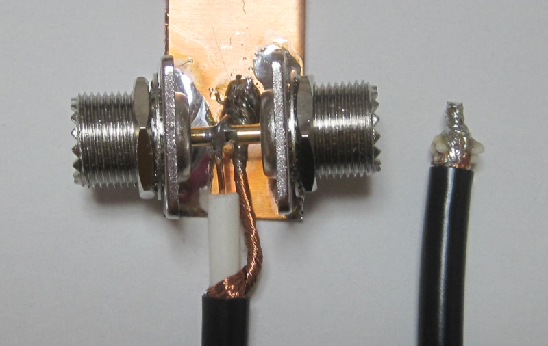
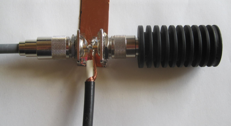
A dummy load is connected to check how the stub is working. The black coax cable forms the stub section, and the gray cable goes to the transmitter.

7MHzDp50ohmWithStub

gnuplot> load "gnuplot.txt"
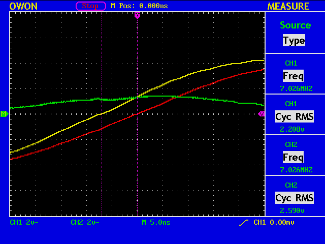
Freq [MHz]=7.026
V1=2.208
V2=2.59
Cursor 1=7e-09
Cursor 2=0.0

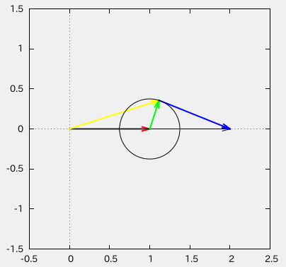
vratio=1.17300724637681
phase1 [deg]=17.70552
phase2 [deg]=0.0

abs(gamma)=0.375575673213821
swr=2.20295016418356
cz={47.3942331949417, 39.368039298651}

7MHzDp50ohmWithSub2

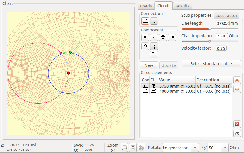
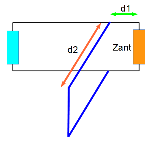
The current length of the stub section using 5C-FV is around 3750mm, and there is a cable of length 1000mm between the impedance bridge and the stub. Assuming the velocity factor of 0.75 for 5C-FV, the expected impedance measured by the impedance bridge is 41.731+j32.604 ohm, which is in good agreement with the cz=47.394+j39.368 ohm.

7MHzDpAnt4

Stub in your shack

capture_002_22092013_191716

A stub (the section in blue) is usually placed near the antenna (orange) to minimize the cable loss. In other words, the parameter d1 is chosen to be the minimum from the set of possible valuse of d1. But sometimes it happens that you have your stub near the transmitter (cyan), that is in your shack.

stubJig

This is a stub section in such cases. The transmitter is on your left side, and the antenna on your right side. (Actually, it can be reversed, because there is no direction.) As you can see, the end of the stub section is short-circuited, but it can be open if you adjust the length d1 properly.

WARNING: Watch out for the HIGH VOLTAGE!