Bug Keys (6)

root

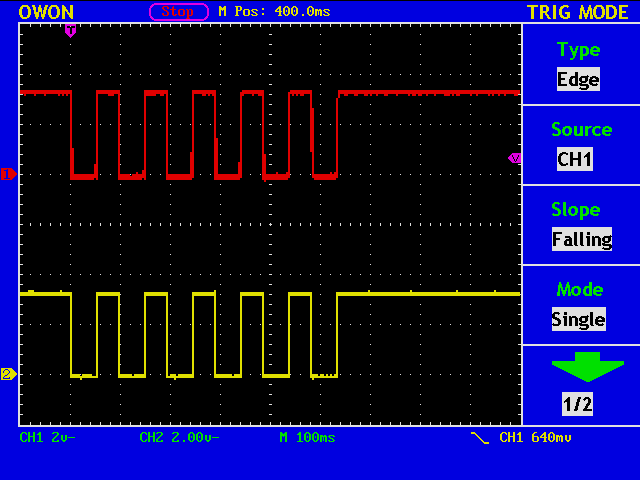
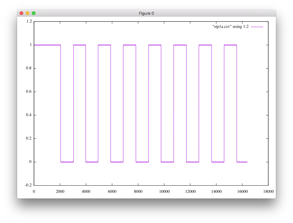
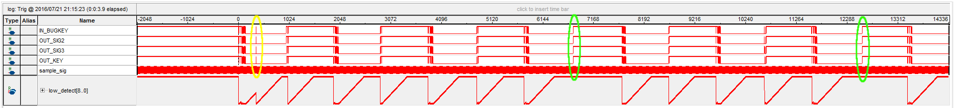
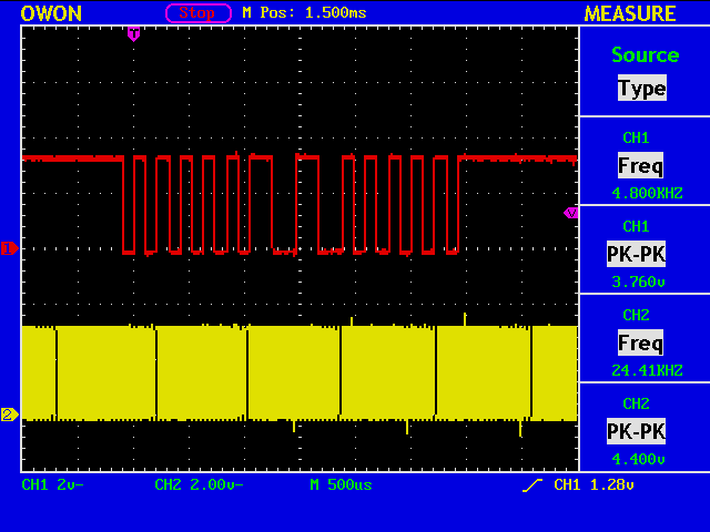
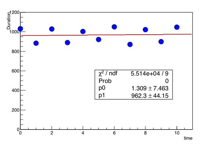
I thought that the dot duration may change in time, but we need more observations to say anything.

// file name = mytest.cc
{
  TCanvas *c = new TCanvas( "test" );
  TH1 *frame = c->DrawFrame( 0.0, 0.0, 11.0, 1200.0 );
  frame->GetXaxis()->SetTitle("time");
  frame->GetYaxis()->SetTitle("Duration");
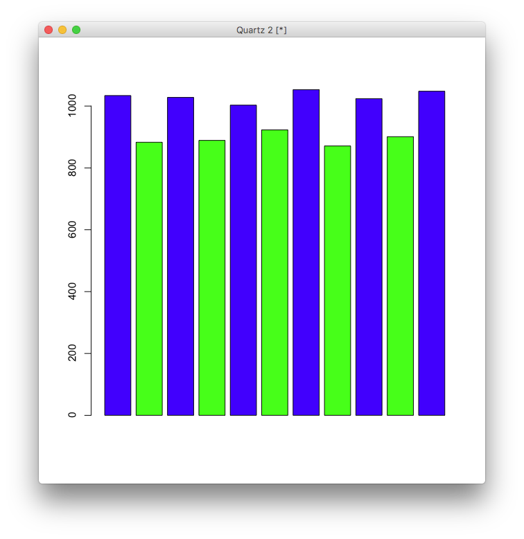
  double x[11] = { 0.0, 1.0, 2.0, 3.0, 4.0, 5.0, 6.0, 7.0, 8.0, 9.0, 10.0 };
  double y[11] = { 1034, 883, 1028, 889, 1003, 923, 1053, 871, 1024, 901, 1048};
  TGraph *g = new TGraph( 11, x, y );
  g->SetMarkerStyle( 20 );
  g->SetMarkerColor(  4 );
  g->SetMarkerSize (  2 );
  g->Draw( "P" );
  TF1 *f1 = new TF1( "f1", "[0]*x+[1]" );
  gStyle -> SetOptFit(1111);
  g->Fit (f1);
}
% root -x mytest.cc
   -------------------------------------------------------------------------
  | Welcome to ROOT 6.06/08                             http://root.cern.ch |
  |                                            (c) 1995-2016, The ROOT Team |
  | Built for macosx64                                                      |
  | From heads/v6-06-00-patches@v6-06-06-30-g3bae07b, Sep 01 2016, 14:28:05 |
  | Try '.help', '.demo', '.license', '.credits', '.quit'/'.q'              |
   -------------------------------------------------------------------------

root [0] 
Processing mytest.cc...

****************************************
Minimizer is Minuit / Migrad
Chi2                      =      55135.1
NDf                       =            9
Edm                       =  2.85319e-19
NCalls                    =           32
p0                        =      1.30909   +/-   7.46271     
p1                        =      962.273   +/-   44.15       
root [1] 

Bug Keys (5)

bugkey10

Now, we are sending six dots, the red trace showing the signal obtained at the dot contact, and the yellow trace out of a simple debounce circuit in an FPGA.

It is easy to include a counter in the device for measuring the length of marks and spaces.

bugkey9

By manually reading the numbers in the above figure, you can write a short script in R.

% R
> dat_v=c(1034, 883, 1028, 889, 1003, 923, 1053, 871, 1024, 901, 1048)
> barplot(dat_v, col=c("blue", "green"))

bugkey11

The blue bars correspond to the mark (=low) length, and the green ones to the space (=high). You will immediately notice that the mark to space ratio is not 1.0, and some more adjustment is required.

Bug Keys (3)

bugkey6

Although the current logic to eliminate the bouncing is far from perfect, let us go on to the next step.

The signals captured using SignalTap II can be exported as, say, a CSV file. Therefore, you can manipulate the data in various ways.

bugkey7

The waveform shows the first eight dots, the last one imcomplete, of consecutive dots.

bugkey8

Each length of marks and spaces is shown as a bar graph. Note that the value of 1,000 corresponds to 50mS.

Bug Keys (2)

bugkey3

If your bug key is connected to an input port of an FPGA, you will observe the signals such as in the figure above. (Please click the figure to enlarge.)

You will notice that in some cases (see the green circles) we do not have contact bounce at the rising edges, but you can not always expect it to be true. Also note that (see the yellow circle) sometimes we have relatively long bouncing.

bugkey4

A simple logic is employed to eliminate those bouncing without introducing a delay. See the signal OUT_KEY.

UART IP Core

uart

You can use IP cores to implement popular functionalities. One example is UART to which stdout is now redirected.

// Nios II - Prog/main.c
while(1) {
    printf("U3U"); // 0x55, 0x33, 0x55
    usleep(10000);

uart3

Qsys is a system integration tool to graphically connect IP functions and subsystems.

uart2

A start bit, eight data bits (LSB first) with no parity bit, and one stop bit.

uart4

MAX 10 and NIOS II

neos

Altera’s Nios II is a 32 bit RISC architecture processor (soft) core that can be embedded into MAX 10 FPGAs.

I am now writing a short C program to check the SDRAM chip on the FPGA board.

sdramcheck

FPGA CW Keyer (12)

dash4

The dot/dash ratio can be different from usual 1:3.

parameter COUNT_DOT   = 32'h0010_0000;
parameter COUNT_DASH  = 32'h0040_0000;
parameter COUNT_SPACE = 32'h0010_0000;
//
if ( shift_reg [5] )
begin
    count_max <= COUNT_DASH;
    count     <= 32'h0000_0000;
    r_state   <=  4'b0001; // next state is DASH
end

The state transition becomes simpler in this way.

shannon

The figure is from the very famous paper by Shannon.

FPGA CW Keyer (11)

cwkeyer

Just doing text to morse code conversion. The source code is not optimised, but it works.

//===========================================================
//  FPGA CW Keyer (MAX10 10M08SAE144C8GES)
//===========================================================
`define POW_ON_RESET_MAX 16'hffff
module FPGA
(
	input  wire CLK48,			// pin  27, 48MHz Clock
	output wire[2:0] LED,		// pin [122:120], LED Output [Green, Blue, Red]
	output wire KEY_OUT			// pin 132, CN2-5, key output
	);

//--------------------------
// Internal Power on Reset
//--------------------------
wire reset_n ;							// Internal Reset Signal
reg  pow_on_reset_n ;					// power-up level = Low
reg  [15:0] pow_on_reset_count ;		// power-up level = Low

always @(posedge CLK48)
begin
	if (pow_on_reset_count != `POW_ON_RESET_MAX)
	begin
		pow_on_reset_n			<= 1'b0;
		pow_on_reset_count	<= pow_on_reset_count + 16'h0001;
	end
	else
	begin
		pow_on_reset_n			<= 1'b1;
		pow_on_reset_count	<= pow_on_reset_count;
	end
end

assign reset_n	= pow_on_reset_n;

//--------- counter for dot clock ---------------------
parameter COUNT_PERIOD = 32'h0010_0000;

reg [31:0] count;
wire count_up /* synthesis keep */;

always @ (posedge CLK48 or negedge reset_n)
begin
	if ( reset_n == 1'b0 )
	begin
		count <= 32'h0000_0000;
	end
	else
	begin
		if ( count == (COUNT_PERIOD - 32'h0000_0001) )
		begin
			count <= 32'h0000_0000;
		end
		else
		begin
			count <= count + 32'h0000_0001;
		end
	end
end

assign count_up   = ( count ==  (COUNT_PERIOD - 1) )? 1'b1 : 1'b0;

//--------- 10-bit morse code table (7-bit data and 3-bit length)
parameter N_CODE = 32;
reg [4:0] morse_code;
reg [9:0] code_pattern;

always @(morse_code)
begin
	case (morse_code)
		5'b0_0000: code_pattern <= 10'b01_00000_010; // a
		5'b0_0001: code_pattern <= 10'b1000_000_100; // b
		5'b0_0010: code_pattern <= 10'b1010_000_100; // c
		5'b0_0011: code_pattern <= 10'b100_0000_011; // d
		5'b0_0100: code_pattern <= 10'b0_000000_001; // e
		5'b0_0101: code_pattern <= 10'b0010_000_100; // f
		5'b0_0110: code_pattern <= 10'b110_0000_011; // g
		5'b0_0111: code_pattern <= 10'b0000_000_100; // h
		5'b0_1000: code_pattern <= 10'b00_00000_010; // i
		5'b0_1001: code_pattern <= 10'b0111_000_100; // j
		5'b0_1010: code_pattern <= 10'b101_0000_011; // k
		5'b0_1011: code_pattern <= 10'b0100_000_100; // l
		5'b0_1100: code_pattern <= 10'b11_00000_010; // m
		5'b0_1101: code_pattern <= 10'b10_00000_010; // n
		5'b0_1110: code_pattern <= 10'b111_0000_011; // o
		5'b0_1111: code_pattern <= 10'b0110_000_100; // p
		5'b1_0000: code_pattern <= 10'b1101_000_100; // q
		5'b1_0001: code_pattern <= 10'b010_0000_011; // r
		5'b1_0010: code_pattern <= 10'b000_0000_011; // s
		5'b1_0011: code_pattern <= 10'b1_000000_001; // t
		5'b1_0100: code_pattern <= 10'b001_0000_011; // u
		5'b1_0101: code_pattern <= 10'b0001_000_100; // v
		5'b1_0110: code_pattern <= 10'b011_0000_011; // w
		5'b1_0111: code_pattern <= 10'b1001_000_100; // x
		5'b1_1000: code_pattern <= 10'b1011_000_100; // y
		5'b1_1001: code_pattern <= 10'b1100_000_100; // z
		5'b1_1010: code_pattern <= 10'b00000_00_101; // 0
		5'b1_1011: code_pattern <= 10'b01111_00_101; // 1
		5'b1_1100: code_pattern <= 10'b00111_00_101; // 2
		5'b1_1101: code_pattern <= 10'b00011_00_101; // 3
		5'b1_1110: code_pattern <= 10'b00001_00_101; // 4
		5'b1_1111: code_pattern <= 10'b1000101__111; // <BK>
		default  : code_pattern <= 10'b00_00000_000; // default
	endcase
end

//--------- morse code state transition and output ------------
reg  [3:0] r_state;
reg key_out;
reg [6:0] shift_reg;
reg [2:0] length;

always @ (r_state)
begin
	case(r_state)
		4'b0000: begin key_out <= 1'b0; end		// idle
		4'b0001: begin key_out <= 1'b1; end		// dash 1
		4'b0010: begin key_out <= 1'b1; end		// dash 2
		4'b0011: begin key_out <= 1'b1; end		// dash 3
		4'b0100: begin key_out <= 1'b0; end		// char space 1
		4'b0101: begin key_out <= 1'b1; end		// dot  1
		4'b0110: begin key_out <= 1'b0; end		// word space 1
		4'b0111: begin key_out <= 1'b0; end		// word space 2
		4'b1000: begin key_out <= 1'b0; end
		4'b1001: begin key_out <= 1'b0; end
		4'b1010: begin key_out <= 1'b0; end
		4'b1011: begin key_out <= 1'b0; end
		4'b1100: begin key_out <= 1'b0; end
		4'b1101: begin key_out <= 1'b0; end
		4'b1110: begin key_out <= 1'b0; end
		4'b1111: begin key_out <= 1'b0; end
	endcase
end

assign KEY_OUT = key_out;

always @ (posedge CLK48 or negedge reset_n)
begin
	if ( reset_n == 1'b0 )
	begin
		r_state <= 4'b0000;
		morse_code <= 5'b0_0000;
	end
	else
	begin
	if(count_up)
	begin
		case (r_state)
			4'b0000:
				begin
					r_state <= 4'b0001;
				end
			4'b0001:
				begin
					r_state <= 4'b0010;
				end
			4'b0010:
				begin
					r_state <= 4'b0011;
				end
			4'b0011:
				begin
					r_state <= 4'b0100;
				end
			4'b0100:
				if(length != 3'b000)
				begin
					if(shift_reg[5]) // not MSB because before shift
					begin
						r_state <= 4'b0001;
					end
					else
					begin
						r_state <= 4'b0101;
					end
					shift_reg <= {shift_reg[5:0], 1'b0};
					length <= length - 3'b001;
				end
				else
				begin
					r_state <= 4'b0110;
				end
			4'b0101:
				begin
					r_state <= 4'b0100;
				end
			4'b0110:
				begin
					shift_reg		<= code_pattern[9:3];
					length	<= code_pattern[2:0] - 3'b001;
					if(morse_code == (N_CODE - 1) )
					begin
						morse_code <= 5'b0_0000;
					end
					else
					begin
						morse_code <= morse_code + 5'b0_0001;
					end
					r_state <= 4'b0111;
				end
			4'b0111:
				begin
					if(shift_reg[6])
					begin
						r_state <= 4'b0001;
					end
					else
					begin
						r_state <= 4'b0101;
					end
				end
			default:
			begin
				r_state <= r_state;
			end
		endcase
	end
	else
	begin
		r_state <= r_state;
	end
	end
end

//----------------
// LED Output
//----------------
reg [2:0] myled   ;

always @(posedge CLK48, negedge reset_n)
begin
	if (reset_n == 1'b0 )
	begin
		myled <= 3'b001;
	end
	else
	begin
		myled <= r_state[2:0];
	end
end
assign LED = ~myled;

//===========================================================
endmodule
//===========================================================