Dipole Antenna

dipole

The DUT is my dipole antenna for 17m band, including the coax cable of about 20m length.

Ant18MHz1

The voltage ratio V2/V1, using CH1 for both measurement, is 4.624 [V] / 2.895 [V] = 1.597, and the phase difference is +3.60 [nS] / 55.25 [nS] * 360.0 = +23.46 [deg].

(%i1) Vs:1.0+%i*0.0;
(%i2) t:(+23.46/360.0)*2.0*%pi;
(%i3) s:1.597/2;
(%i4) V2:s*(cos(t)+%i*sin(t));
(%i5) Vr:Vs-V2;
(%i6) z:50.0*(V2/Vr);
(%i7) float(realpart(z));
(%o7) 27.48700095398715
(%i8) float(imagpart(z));
(%o8) 92.08160857471663
(%i9) float(realpart(z)/50.0);
(%o9) 0.54974001907974
(%i10) float(imagpart(z)/50.0);
(%o10) 1.841632171494333

(%i1) zl:z/50.0;
(%i2) g:(zl-1)/(zl+1);
(%i3) float(abs(g));
(%o3) 0.78767422999205
(%i4) VSWR:(1+abs(g))/(1-abs(g));
(%i5) float(VSWR);
(%o6) 8.419487798985081

smith1

Vertical Gain

18MHzcalib1

Checking the voltage at “V1” with both channels. CH2 (yellow) is inverted, and the green trace is CH1-CH2.

18MHzcalib2

Checking the voltage at “V2”. The vertical gains of CH1 and CH2 differ 3.34dB.

OWON PDS5022S (fs=100MHz, 8-bit, 25MHz BW).

Device Under Test (5)

With the same DUT, the frequency of the SG is set to 10120kHz. The voltage ratio is V2/V1 = 1.128 [V] / 2.304 [V] = 0.4896. The phase difference is 18.20 [nS] / 98.81 [nS] * 360.0 = 66.31 [deg].

10MHz1

10MHz2

LTspice simulation at 10120kHz gives the volotage ratio of 2.56 [V] / 5.00 [V] = 0.512, and the phase difference of 17.7 [nS] / 98.81 [nS] * 360.0 = 64.48 [deg].

ltspice10120

(%i1) Vs:1.0+%i*0.0;
(%i2) t:(-66.31/360.0)*2.0*%pi;
(%i3) s:0.4896/2;
(%i4) V2:s*(cos(t)+%i*sin(t));
(%i5) Vr:Vs-V2;
(%i6) z:50.0*(V2/Vr);
(%i7) float(realpart(z));
(%o7) 2.226027166429141
(%i8) float(imagpart(z));
(%o8) -12.98472809821215
(%i9) y:1/z;
(%i10) float(1/realpart(y));
(%o11) 77.96776398223048
(%i12) float(1/imagpart(y));
(%o12) 13.36634540341878
(%i13) float(1/(2.0*%pi*10120e3*(1/imagpart(y))));
(%o13) 1.1765948401104063*10^-9

With the same DUT, the frequency of the SG is set to 18100kHz. The voltage ratio is V2/V1 = 320.1 [mV] / 2.119 [V] = 0.1510. The phase difference is 12.40[nS] / 55.24[nS] * 360.0 = 80.81 [deg].

18MHz1

18MHz2

LTspice simulation at 18100kHz gives the volotage ratio of 1.58 [V] / 5.00 [V] = 0.316, and the phase difference of 11.6 [nS] / 55.24 [nS] * 360.0 = 75.60 [deg].

ltspice18100

(%i1) Vs: 1.0+%i*0.0;
(%i2) t:(-80.81/360.0)*2.0*%pi;
(%i3) s:0.1510/2.0;
(%i4) V2:s*(cos(t)+%i*sin(t));
(%i5) Vr:Vs-V2;
(%i6) z:50.0*(V2/Vr);
(%i7) float(realpart(z));
(%o7) 0.32385259041389
(%i8) float(imagpart(z));
(%o8) -3.796459497712614
(%i9) y:1/z;
(%i10) float(1/realpart(y));
(%o10) 44.82899210266004
(%i11) float(1/imagpart(y));
(%o11) 3.824085368706621
(%i12) float(1/(2.0*%pi*18100e3*(1/imagpart(y))));
(%o12) 2.2993970925737322*10^-9

Device Under Test (4)

bridge

From the measured parameters that the voltage ratio V2/V1 is 0.698 and the phase difference is -57.7 [deg], you can write a vector diagram.

vectorZ1

And from the diagram:

(%i1) Vs:1.0+%i*0.0;
(%i2) t:(-57.7/360.0)*2.0*%pi;    <- measured phase difference
(%i3) s:0.698/2.0;                <- measured voltage ratio times 1/2
(%i4) V2:s*(cos(t)+%i*sin(t));
(%i5) Vr:Vs-V2;                   <- voltage across R6
(%i6) z:50.0*(V2/Vr);             <- R6 is a 50 [phm] resistor
(%i7) float(realpart(z));
(%o7) 4.319309419115194
(%i8) float(imagpart(z));
(%o8) -19.69733542559636
(%i9) y:1/z;
(%i10) 1/realpart(y);
(%o10) 94.14602759832886          <- nominal 100 [ohm]
(%i11) 1/imagpart(y);
(%o12) 20.64445990101613
(%i28) float(1/(2.0*%pi*7026e3*(1/imagpart(y))));
(%o28) 1.0972572543782682*10^-9   <- nominal 1 [nF]

Device Under Test (3)

ltspice2

LTspice simulation results is shown with the same DUT (100 [ohm] // 1 [nF]).

ltspice1

The voltage ratio is 3.50 [V] / 5.00 [V] = 0.70, and the phase difference is 21.48 [nS], both reasonably close to the actual measurement results.

Device Under Test (2)

cursor2

Now, let’s try again with another DUT.

cursor1

This time there is a phase difference, so we must determine complex impedance in the form Z = R + jX.

cursor

The voltage ratio is: V2/V1 = 1.713 [v] / 2.453 [v] = 0.698, and the phase difference is: 360.0 [deg] * (-22.80 [nS] / 142.32 [nS]) = -57.7 [deg], where 142.32 [nS] is the period for 7026kHz.

Assuming you know the answer that the DUT is 100 [ohm] // 1 [nF], the voltage ratio and the phase are obtained in the following manner. (This is a reverse way.)

(%i1) r6:50;
(%i2) r:100;                      <- here is your 100 [ohm]
(%i3) x:1/(%i*2*%pi*7026e3*1e-9); <- here is your 1 [nF]
(%i4) z:r*x/(r+x);
(%i5) v2:z/(z+r6);
(%i6) float(2*abs(v2));
(%o6) 0.74942127142784            <- voltage ratio
(%i7) float(carg(v2)*360/(2*%pi));
(%o7) -55.80120705365476          <- phase difference

In most cases you do not the answer in advance, so you must go like this:

(%i1) t:(-57.7/360.0)*2.0*3.16; <- measured phase difference
(%i2) v:0.698/2.0;              <- measured voltage ratio
(%i3) r:50.0;
(%i4) float(solve([(R*(r+R)+X^2)/((r+R)^2+X^2)=v*cos(t),r*X/((r+R)^2+X^2)=v*sin(t)],[R,X]));
(%o4) [[R=-50.0,X=0.0],[R=4.183382859001799,X=-19.67880950916058]]
(%i5) Z:4.1833-19.6788*%i;
(%i6) Y:1/Z;
(%i7) 1/realpart(Y);
(%o7) 96.75499446131043         <- Real part of Z (nominal 100 [ohm])
(%i8) 1/imagpart(Y);
(%o8) 20.56808181037462         <- Imaginary part of Z
(%i9) C:1/(2.0*3.1416*7026e3*1/imagpart(Y)); <- convert to capacitance
(%o9) 1.1013292647891441*10^-9  <- 1.1 [nF] (nomnal 1 [nF])

To verify the above result, we go again the reverse way:

(%i1) r6:50;
(%i2) r:96.755;                        <- R=96.755 [ohm]
(%i3) x:1/(%i*2*%pi*7026e3*1.1013e-9); <- C=1.1013 [nF]
(%i4) z:r*x/(r+x);
(%i5) v2:z/(z+r6);
(%i6) float(2*abs(v2));
(%o6) 0.69801459091613                <- voltage ratio
(%i7) float(carg(v2)*360/(2*%pi));
(%o7) -58.03754068937465              <- phase difference

Not bad?

Device Under Test

attbridge

With a signal generator (SG), you can make a measurement of various parameters of your device. One example is impedance measurement.

bridge

A fixed attenuator is inserted in front to improve the souce match. For 6dB attenuation, use R1=39 [ohm], R2=R3=150 [ohm]. “X” is the device under test (DUT), and R4=R5=R6=50 [ohm]. In the photograph, a 100 [ohm] resistor is employed as a DUT.

dut100ohm

IC-7410 with tx frequency 7026kHz is used as a SG. RF power is minimized to 2 [W]. CH1 (in red) shows “V1”, and CH2 (in yellow) shows “V2”.

xy

Since the DUT, a 100 [ohm] resistor, is pure resistive, there is no phase difference between the two waveforms.

solve

By solving a simple equation, we conclude that the impedance of our DUT is 94.6 + j*0 [ohm].

IF Filter

Fl-431

FL-431 is an optional first stage IF filter for ICOM IC-7410. Its bandwidth is 3kHz and should be effective when there is a strong adjacent inband signal. The empty slot is for FL-430 (another optional filter with bandwidth 6kHz), which I didn’t care to buy. The default 15kHz IF filter is just next to the empty slot.

Fl-431panel

IC-7410 Keyspeed

A short program to check the data format for IC-7410 Keyspeed control.

#define MYRIG &quot;/dev/ttyUSB0&quot;
int fd = open(MYRIG, O_RDWR | O_NOCTTY);
output[0] = 0xfe; /* IC-7410 preamble */
output[1] = 0xfe; /* IC-7410 preamble */
output[2] = 0x80; /* IC-7410 CI-V address */
output[3] = 0x00; /* my PC address (any) */
output[4] = 0x14; /* IC-7410 command for set params */
output[5] = 0x0c; /* IC-7410 sub-command for keyspeed inquiry */
output[6] = 0xfd; /* IC-7410 postamble */
outputcount = 7; /* command length */
writecount = write(fd, &amp;output, outputcount);

This is the inquiry and its response with different settings of the keyspeed volume.

[FE] [FE] [80] [00] [14] [0C] [FD]
[FE] [FE] [00] [80] [14] [0C] [00] [01] [FD] <- volume at min. ( 6 wpm)
[FE] [FE] [00] [80] [14] [0C] [01] [28] [FD] <- volume at center
[FE] [FE] [00] [80] [14] [0C] [02] [54] [FD] <- volume at max. (48 wpm)

Set several predefined keyspeed through the function keys.

void send_keyspeed(int wpm) { /* IC-7410 key speed */
static char output_ks [9] =
{0xfe, 0xfe, 0x80, 0x00, 0x14, 0x0c,
0x01, 0x28, /* from 0x00,0x00 to 0x02,0x55 */
0xfd};
switch(wpm) {
case 1 : output_ks[6] = 0x00; output_ks[7] = 0x64;break;
case 2 : output_ks[6] = 0x00; output_ks[7] = 0x96;break;
case 3 : output_ks[6] = 0x01; output_ks[7] = 0x28;break;
case 4 : output_ks[6] = 0x01; output_ks[7] = 0x92;break;
}
write(fd, output_ks, 9);
}

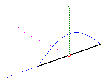
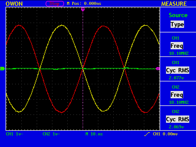
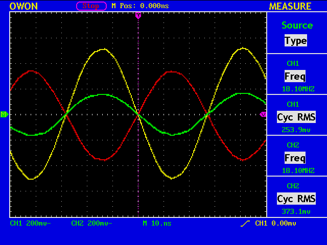
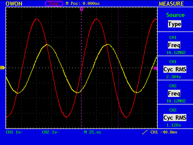
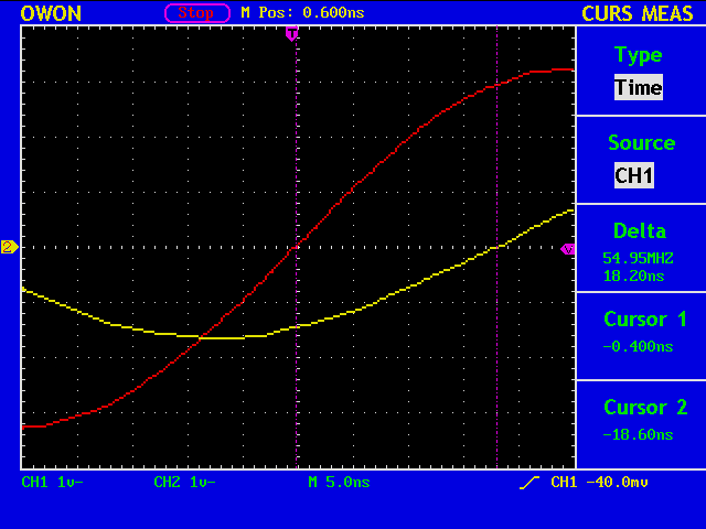
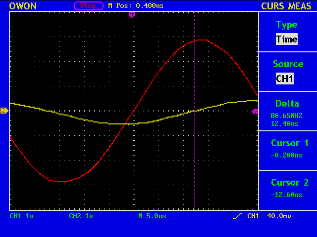
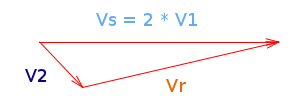
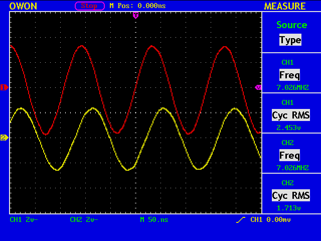
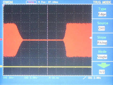
By sending a series of dots at each speed, the element length is obtained by observing the waveform of the audio signal, and WPM is obtained by using the equation: WPM=1200/element_length [mS].

keyspeed

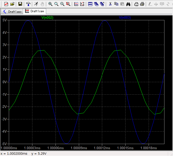
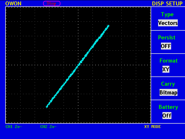
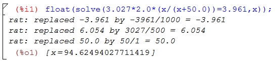
The measured curve (in red) differs slightly from a liner interpolation (in green) by the two points suggested by the manual, (0: 6 wpm, 255: 48 wpm). In either case, the parameters for {20|25|30|35} wpm shall be around {83, 112, 141, 170}, respectively.

So, in conclusion, a new version of the source code for CW Keybord is:

/* file name = ic7410m.c */
/* % gcc ic7410m.c -o ic7410m -lncurses */
#include <ncurses.h>
#include <unistd.h>
#include <stdio.h>
#include <stdlib.h>
#include <termios.h>
#include <string.h>
#include <fcntl.h>
#define BUFSIZE 4096
#define BAUDRATE B19200
#define MYRIG "/dev/ttyUSB0"

int fd=-1;

void send_cw(char* text);

void send_keyspeed(int wpm) { /* IC-7410 key speed */
static char output_ks [9] =
{0xfe, 0xfe, 0x80, 0x00, 0x14, 0x0c,
0x01, 0x28, /* from 0x00,0x00 to 0x02,0x55 */
0xfd};

switch(wpm) { /* 20, 25, 30, 35 wpm */
case 1 : output_ks[6] = 0x00; output_ks[7] = 0x83;break;
case 2 : output_ks[6] = 0x01; output_ks[7] = 0x12;break;
case 3 : output_ks[6] = 0x01; output_ks[7] = 0x41;break;
case 4 : output_ks[6] = 0x01; output_ks[7] = 0x70;break;
}

write(fd, output_ks, 9);
}

void send_cw(char* text) { /* IC-7410 send CW */
static char output [BUFSIZE] = {0xfe, 0xfe, 0x80, 0x00, 0x17};
char *p;
int count;

count=0; p=output+5;
while(*p++ = *text++) {
count++;
if(count == 30) { /* IC-7410 max CW text length */
*p = 0xfd; /* IC-7410 postamble */
write(fd, output, 5+count+1);
count=0; p=output+5;
}
}
if(count) {
*(--p) = 0xfd; /* replace zero with postamble */
write(fd, output, 5+count+1);
}
}

void send_stored_text(int id) { /* use Function Keys */
static char *text_array[]={
"cq cq cq de jh1ood jh1ood jh1ood k ", /* F1 */
"qrz? de jh1ood k ", /* F2 */
"ur 5nn ^bk ", /* F3 */
"73 tu e e "}; /* F4 */

send_cw(text_array[id-1]); /* id=1, 2, ... */
attron(COLOR_PAIR(2)); printw (text_array[id-1]); attroff(COLOR_PAIR(2));
}

void serial_init(void) {
struct termios tio;
memset(&tio, 0, sizeof(tio));
tio.c_cflag = CS8 | CLOCAL | CREAD;
tio.c_cc[VTIME] = 0;
tio.c_cc[VEOL ] = 0xfd; /* IC-7410 postamble */
tio.c_lflag = ICANON;
tio.c_iflag = IGNPAR | ICRNL;
cfsetispeed(&tio, BAUDRATE);
cfsetospeed(&tio, BAUDRATE);
tcsetattr (fd, TCSANOW, &tio);
}

int main (void) {
int c, i, count=0, nrow, ncol, row=0, col=0;
char word[BUFSIZE];
struct termios oldtio;

fd = open(MYRIG, O_RDWR | O_NOCTTY);
if (fd < 0) {
fprintf(stderr,"Error: can not open %s n", MYRIG);
return (-1);
}
tcgetattr (fd, &oldtio);
serial_init();

initscr (); /* ncurses init */
raw ();
noecho ();
keypad (stdscr, TRUE);
scrollok (stdscr, TRUE);
getmaxyx (stdscr,nrow,ncol);
start_color();
init_pair (1, COLOR_RED , COLOR_BLACK);
init_pair (2, COLOR_YELLOW, COLOR_BLACK);
attron (COLOR_PAIR(1)); printw("CW keyboard.."); attroff(COLOR_PAIR(1));
row=2; col=0; move(row, col);
refresh ();

while ( (c=getch()) != 0x04) { /* EOT */
switch (c) {
case KEY_F(1): send_stored_text(1); break;
case KEY_F(2): send_stored_text(2); break;
case KEY_F(3): send_stored_text(3); break;
case KEY_F(4): send_stored_text(4); break;
case KEY_F(5): send_keyspeed (1); break;
case KEY_F(6): send_keyspeed (2); break;
case KEY_F(7): send_keyspeed (3); break;
case KEY_F(8): send_keyspeed (4); break;
case KEY_BACKSPACE:
if(count) { /* only within a word */
getyx (stdscr, row, col);
count--; col--; /* only within the same line */
mvaddch(row, col, ' ');
move (row, col); /* cursor goes back */
}
break;
default:
if(isprint(c)) {
addch(c);
word[count++] = c;
}
break;
}

getyx(stdscr, row, col);
if(c == 0x0a || c==' ' && col >= ncol-10 || col == ncol)
printw("n");
refresh();

if(c == 0x0a || c == ' ' || c == '.' || c == ',') {
word[count] = 0; count=0;
send_cw(word);
}
}

tcsetattr(fd, TCSANOW, &oldtio); /* reset serial terminal */
endwin (); /* reset ncurses */
return EXIT_SUCCESS;
}