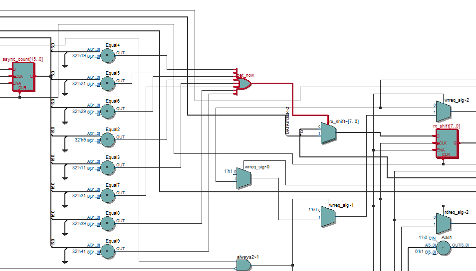
Sometimes it is helpful to use one of the Netlist Viewers.
// FPGA
if(get_now == 1'b1) begin
rx_shift <= {rx2, rx_shift[7:1]}; //LSB first
end
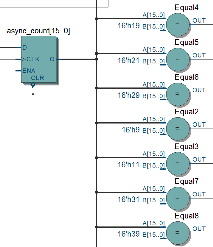
assign get_now = (async_count == 9 || async_count == 17 || async_count == 25
|| async_count == 33 || async_count == 41 || async_count == 49
|| async_count == 57 || async_count == 65 )? 1'b1 : 1'b0;
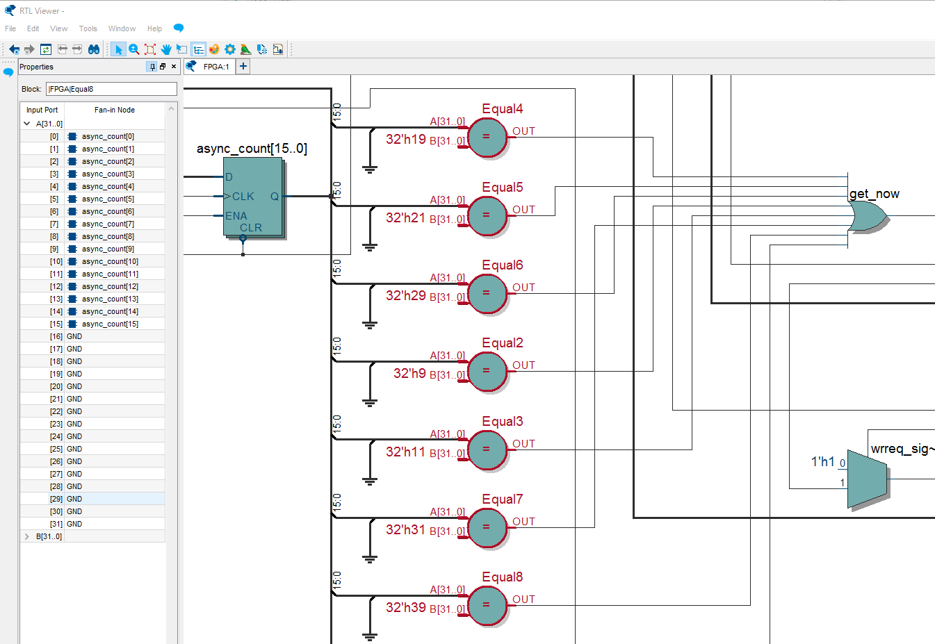
How come the comparators, Equal*, are with the 32-bit width? Yes, in Verilog the integers are considered to be the type signed 32-bit. I should have explicitly written 16’h9, 16’h11, etc.
assign get_now = (async_count == 16'h9  || async_count == 16'h11 || async_count == 16'h19
               || async_count == 16'h21 || async_count == 16'h29 || async_count == 16'h31
               || async_count == 16'h39 || async_count == 16'h41 )? 1'b1 : 1'b0;
Voilà!