FPGA CW Keyer (7)

cwkeyer

Not perfect, but usable. How can I change the speed? It is easy. Just edit the source code and re-compile.

parameter DOT_PERIOD = 5000000;

sidetone

A sidetone oscillator is included.

assign OUT_SOUND = ( OUT_KEY && (sound > SOUND_PERIOD/2) )? 1'b1 : 1'b0;

FPGA Evaluation Kit (4)

usbblaster

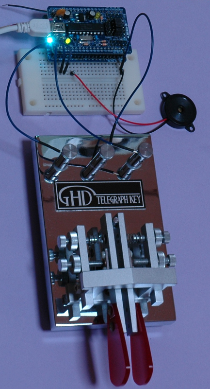
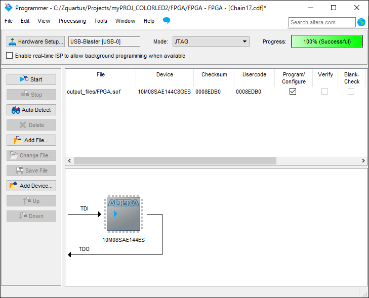
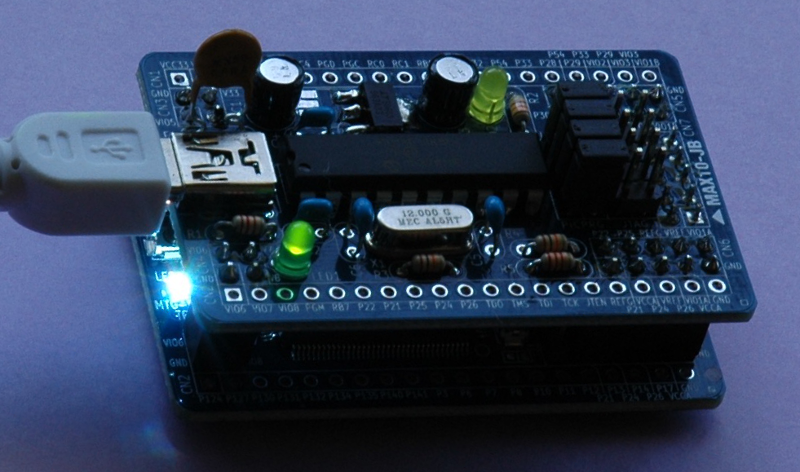
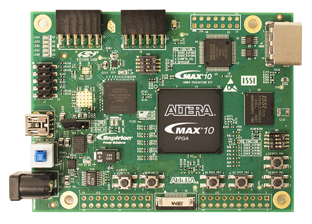
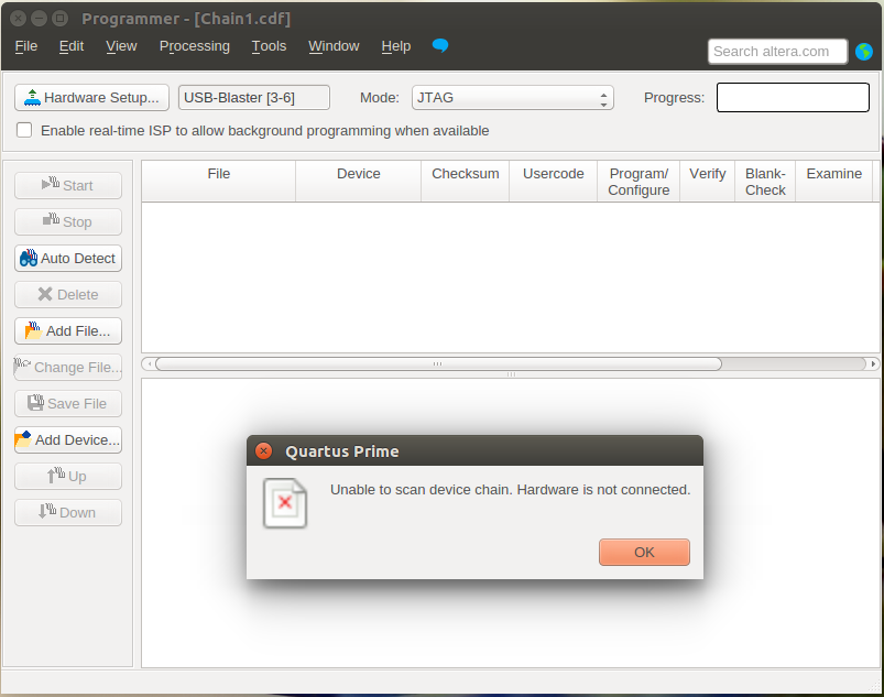
The PIC board, MAX10-JB,should work as a USB-Blaster download cable, but it seems that something is wrong somewhere.

% dmesg
[   99.874756] usb 3-6: new full-speed USB device number 5 using xhci_hcd
[  100.005217] usb 3-6: New USB device found, idVendor=09fb, idProduct=6001
[  100.005224] usb 3-6: New USB device strings: Mfr=1, Product=2, SerialNumber=3
[  100.005229] usb 3-6: Product: USB-Blaster
[  100.005232] usb 3-6: Manufacturer: Altera

% lsusb
Bus 003 Device 005: ID 09fb:6001 Altera Blaster

% sudo ./jtagd --foreground --debug
JTAG daemon started
Using config file /etc/jtagd/jtagd.conf
Remote JTAG permitted when password set
USB-Blaster added "USB-Blaster [3-6]"

USB-Blaster port (/dev/bus/usb/003/005) opened

% ls -l /dev/bus/usb/003/005
crw-rw-rw- 1 root root 189, 260 May 18 16:30 /dev/bus/usb/003/005

% cat /etc/udev/rules.d/51-usbblaster.rules 
# Altera USB-Blaster for Quartus FPGA Software 
SUBSYSTEMS=="usb", ATTR{idVendor}=="09fb", ATTR{idProduct}=="6001", MODE="0666" 
SUBSYSTEMS=="usb", ATTR{idVendor}=="09fb", ATTR{idProduct}=="6002", MODE="0666" 
SUBSYSTEMS=="usb", ATTR{idVendor}=="09fb", ATTR{idProduct}=="6003", MODE="0666" 

FPGA Evaluation Kit (3)

extpow

Receiving DC power (+5V) via USB I/F is somewhat complicated due to various standard and custom protocols employed. Sometimes D+ and D- lines are used to convey information.

dcp

maxim2

https://www.maximintegrated.com/en/app-notes/index.mvp/id/5801

tps2540

http://www.ti.com/lit/ds/symlink/tps2540a.pdf

This causes a problem with the PIC board, MAX10-JB, because some of the I/O pins of the PIC microcontroller are used both for D+ and D- lines for USB I/F, and for writing into its flash program memory.

To avoid interference, I pulled off the USB cable and used an external power supply just while programming the flash memory.

The green flushing LED on the FPGA evaluation board, MAX10-FB, shows that the flash memory was successfully programmed and the verification was OK.

Recommended Practices (2)

4-state-moore-vlog

Here is an HDL design example given by Altera.

https://www.altera.co.jp/support/support-resources/design-examples/design-software/verilog/ver-state-machine.html

// 4-State Moore state machine

// A Moore machine's outputs are dependent only on the current state.
// The output is written only when the state changes.  (State
// transitions are synchronous.)

module moore_mac
(
	input	clk, data_in, reset,
	output reg [1:0] data_out
);
	
	// Declare state register
	reg		[1:0]state;
	
	// Declare states
	parameter S0 = 0, S1 = 1, S2 = 2, S3 = 3;
	
	// Output depends only on the state
	always @ (state) begin
		case (state)
			S0:
				data_out = 2'b01;
			S1:
				data_out = 2'b10;
			S2:
				data_out = 2'b11;
			S3:
				data_out = 2'b00;
			default:
				data_out = 2'b00;
		endcase
	end
	
	// Determine the next state
	always @ (posedge clk or posedge reset) begin
		if (reset)
			state <= S0;
		else
			case (state)
				S0:
					state <= S1;
				S1:
					if (data_in)
						state <= S2;
					else
						state <= S1;
				S2:
					if (data_in)
						state <= S3;
					else
						state <= S1;
				S3:
					if (data_in)
						state <= S2;
					else
						state <= S3;
			endcase
	end
	
endmodule

You can copy and paste such example codes, or can insert the code from a template if you are using Quartus Prime.

template

FPGA Evaluation Kit (2)

LED

A PIC board, MAX10-JB, is plugged on top of the FPGA evaluation board, MAX10-FB. A bright white LED is flushing to indicate that the pre-mounted FPGA is working fine with a pre-programmed configuration.

The PIC board works like an Altera’s USB-Blaster Download Cable.

FPGA Evaluation Kit

max_10m50m_front

Various kinds of evaluation kits are available. This board is from Altera and looks very nice with on-board HDMI output capability.
https://www.altera.com/products/boards_and_kits/dev-kits/altera/kit-max-10m50-evaluation.html

max10

Here is the board I am going to use. An FPGA, Altera’s MAX 10 (10M08SAE144C8G), is pre-mounted, but you need to solder other parts, such as a 256kbit SDRAM, and a 48MHz Xtal oscillator.

More detailed description of the board is here.
(No, I don’t think they have pages written in English.)