So I found it to be very useful. This is especially true when one does not have a logic analyzer.
https://www.altera.com/content/dam/altera-www/global/en_US/pdfs/literature/hb/qts/qts_qii5v3.pdf

Ham Radio Blog
So I found it to be very useful. This is especially true when one does not have a logic analyzer.
https://www.altera.com/content/dam/altera-www/global/en_US/pdfs/literature/hb/qts/qts_qii5v3.pdf

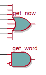
Keep synthesis is a Verilog HDL synthesis attribute. You can use this attribute to keep a combinational node so you can observe the node with the SignalTap II Logic Analyzer.
wire get_now  /* synthesis keep */ ;
wire get_word /* synthesis keep */ ;

assign get_now = (async_count == 7'h9  || async_count == 7'h11 || async_count == 7'h19
               || async_count == 7'h21 || async_count == 7'h29 || async_count == 7'h31
               || async_count == 7'h39 || async_count == 7'h41 )? 1'b1 : 1'b0;
assign get_word = (idle1 == 1'b1 && idle2 == 1'b0)? 1'b1 : 1'b0;
Other usefull attributes are: /* synthesis noprune */, and /* synthesis preserve */ for registers.
http://quartushelp.altera.com/15.0/mergedProjects/hdl/vlog/vlog_file_dir.htm
Sometimes it is helpful to use one of the Netlist Viewers.
// FPGA
if(get_now == 1'b1) begin
    rx_shift <= {rx2, rx_shift[7:1]}; //LSB first
end

assign get_now = (async_count ==  9 || async_count == 17 || async_count == 25
               || async_count == 33 || async_count == 41 || async_count == 49
               || async_count == 57 || async_count == 65 )? 1'b1 : 1'b0;
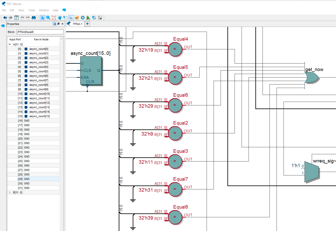
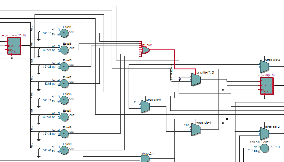
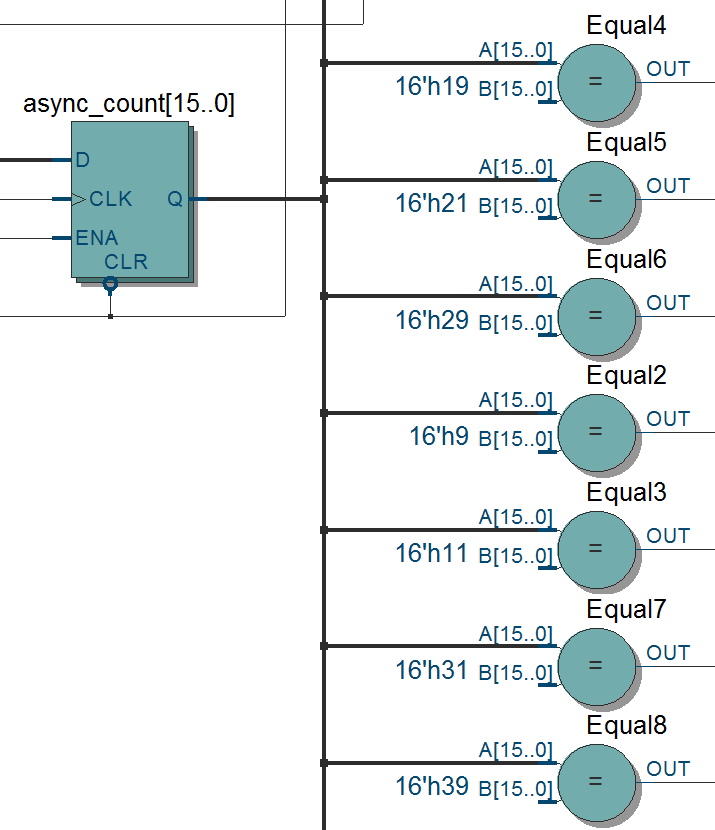
How come the comparators, Equal*, are with the 32-bit width? Yes, in Verilog the integers are considered to be the type signed 32-bit. I should have explicitly written 16’h9, 16’h11, etc.
assign get_now = (async_count == 16'h9  || async_count == 16'h11 || async_count == 16'h19
               || async_count == 16'h21 || async_count == 16'h29 || async_count == 16'h31
               || async_count == 16'h39 || async_count == 16'h41 )? 1'b1 : 1'b0;
Voilà!
https://www.altera.com/en_US/pdfs/literature/ug/ug_fifo.pdf
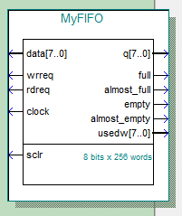
If you receive some data, say via a serial interface, you may wish to temporarily store the received data in a FIFO.
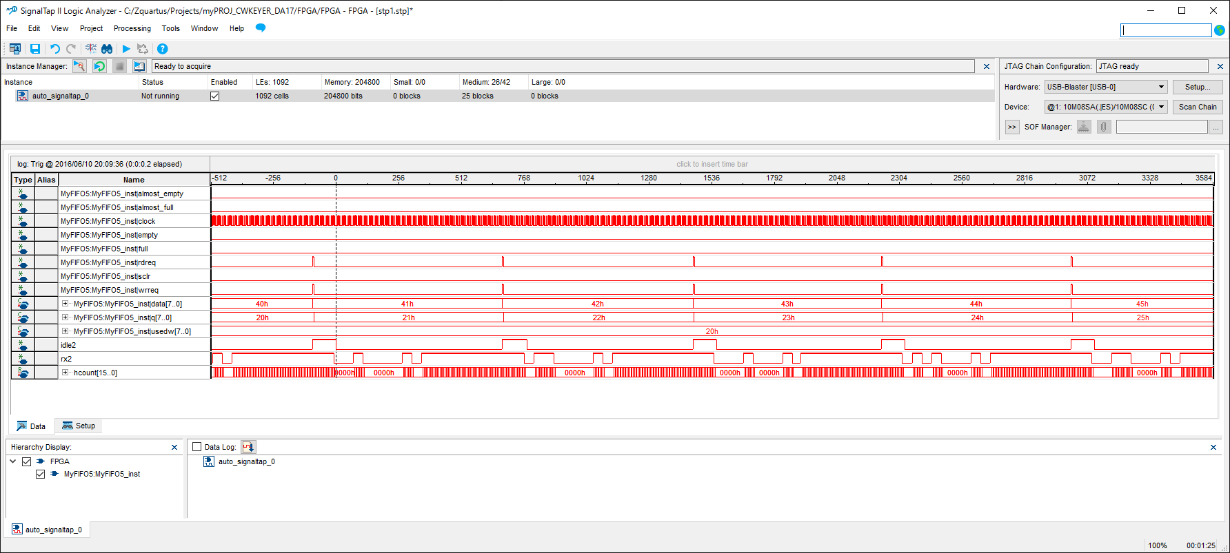
A sequence of data, 40h, 41h, 42h, … is fed into a 256 words FIFO, and a delayed sequence of 20h, 21h, 22h, …is coming out of the FIFO.
if (! almost_empgy) rdreq <= 1'b1;
defparam
  scfifo_componet.almost_emtpy_value = 32; // hex 20
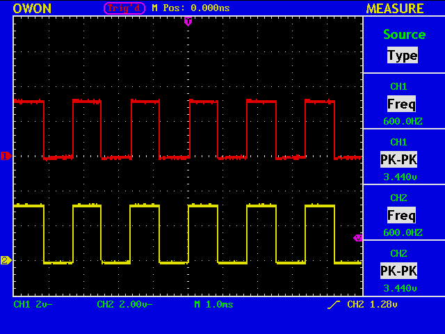
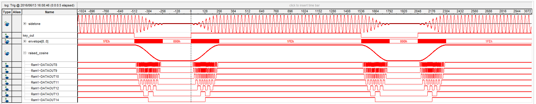
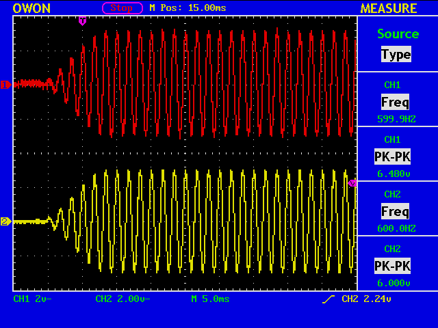
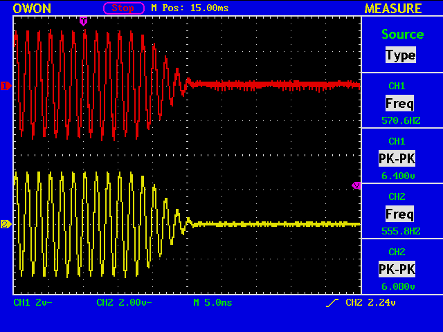
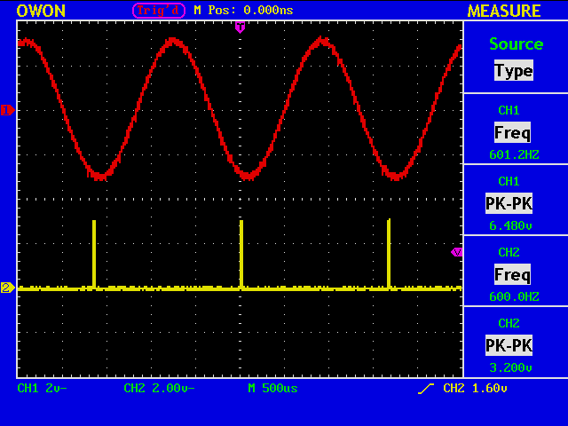
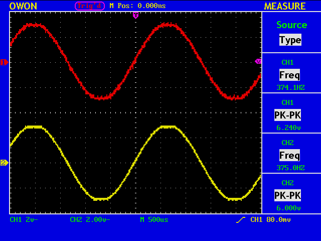
A simple verison of a numerically controlled oscillator is implemented, and a 600Hz sine wave is generated. The red trace shows the MSB to the D/A converter.
//--------- 16-bit phase accumulator ---------------------
reg [15:0] phase_acc;
reg [15:0] phase_delta;

always @ (posedge clk_myown or negedge res_n)
begin
  if ( res_n == 1'b0 ) begin
     phase_acc   <= 16'h0000;
     phase_delta <= 16'h0040;
  end
  else if (daword_up == 1'b1) begin // 48kHz
     phase_delta <= (1'b0)? {5'b0_0000, rx_data, 3'b000} : 16'b0000_0011_0011_0011;
     phase_acc <= phase_acc + phase_delta;
     sound_index <= phase_acc[15:7];
  end
end
The Line 12 shows that the frequency control word (FCW), phase_delta, can be given via a serial interface.
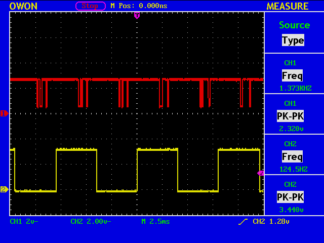
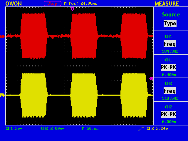
Now sending the value of an 8-bit counter with a serial interface. The yellow trace shows the LSB of the received word.
// Arduino
void setup() {
  Serial.begin(9600); //default 8-bit no parity, one stop bit
  while (!Serial) {
    ; // wait for serial port to connect. Needed for native USB port only
  }
 }

int thisByte = 0x00;

void loop() {
  Serial.write(thisByte);
  delay(4);
  thisByte = thisByte + 1;
  if(thisByte == 256) thisByte = 0;
}
// FPGA
if(get_now == 1'b1) begin
    rx_shift <= {rx2, rx_shift[7:1]}; //LSB first
end

assign get_now = (async_count ==  9 || async_count == 17 || async_count == 25
               || async_count == 33 || async_count == 41 || async_count == 49
               || async_count == 57 || async_count == 65 )? 1'b1 : 1'b0;
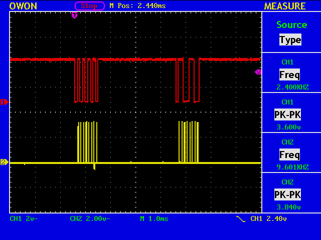
Serial interface is a simple way to communicate between your PC and your device, including an FPGA. An Arduino board is used as a USB-to-serial converter, sending a word 8’b1010_1010 and 8’b1100_1100 alternatively.
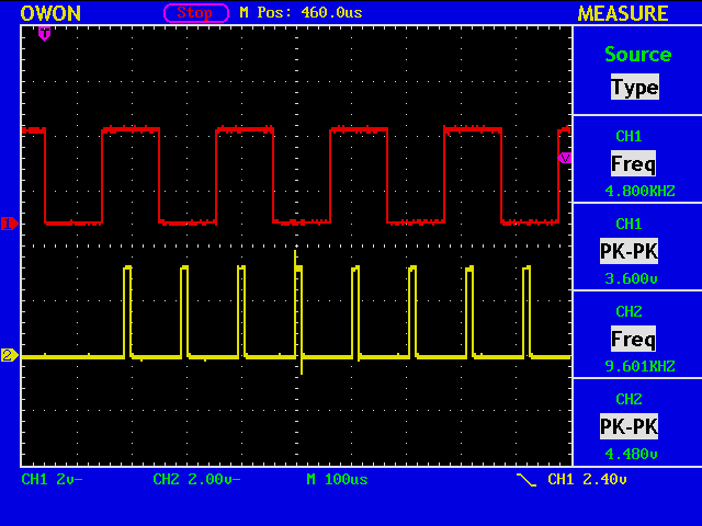
A simple logic in an FPGA generates a sampling pulse for the serial data. Note that the first “0” is a start bit, which does not have to be sampled.
Using a PCM5102A dac with typical performance of SNR 112dB, Dynamic Range 112dB, THD+N@-1dBFS -93dB.
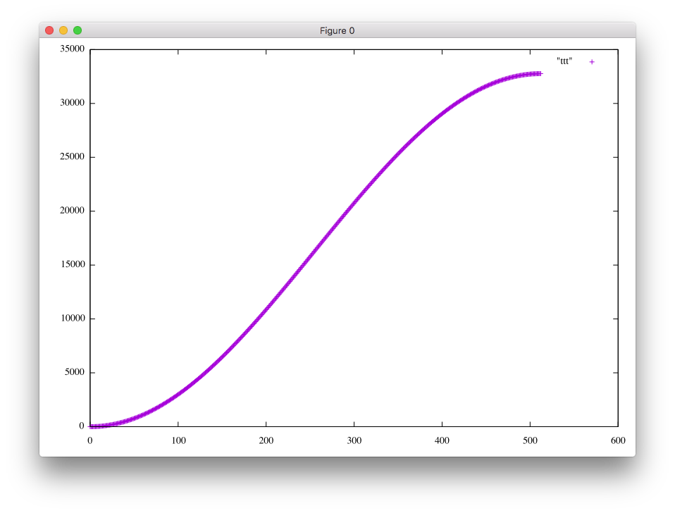
The envelope is shaped as a raised cosine over 512 samples at Fs=48kHz.
reg signed [15:0] sine_table;
always @(sound_index) begin
    case (sound_index)
        7'b0000000: begin sine_table <= 16'b0000000000000000; end //      0:         0
//
        7'b1001111: begin sine_table <= 16'b1111010111110110; end //     79:     -2570
reg signed [15:0] shape;
always @(envelope) begin
    case (envelope)
        9'b 000000000 : begin shape <= 16'b0000000000000000; end //   0:     0
//
        9'b 111111111 : begin shape <= 16'b0111111111111110; end // 511: 32766
reg signed [31:0] mult; // sine_table: signed 16bit, shape: signed 16-bit
always @(sound_index) begin
   mult <= shape * sine_table;
end
always @ (posedge clk_myown or negedge res_n)
 begin
  if ( res_n == 1'b0 )
   daword <= 6'b00_0000;
  else begin
   daword <= daword + 6'b00_0001;
   if ( daword[4:0] == 5'b0_0000 ) // for each 32-bit, or for each L and R
	dadata <= {mult[30:0], 1'b0};
   else
	dadata <= {dadata[30:0], 1'b0};
  end
 end
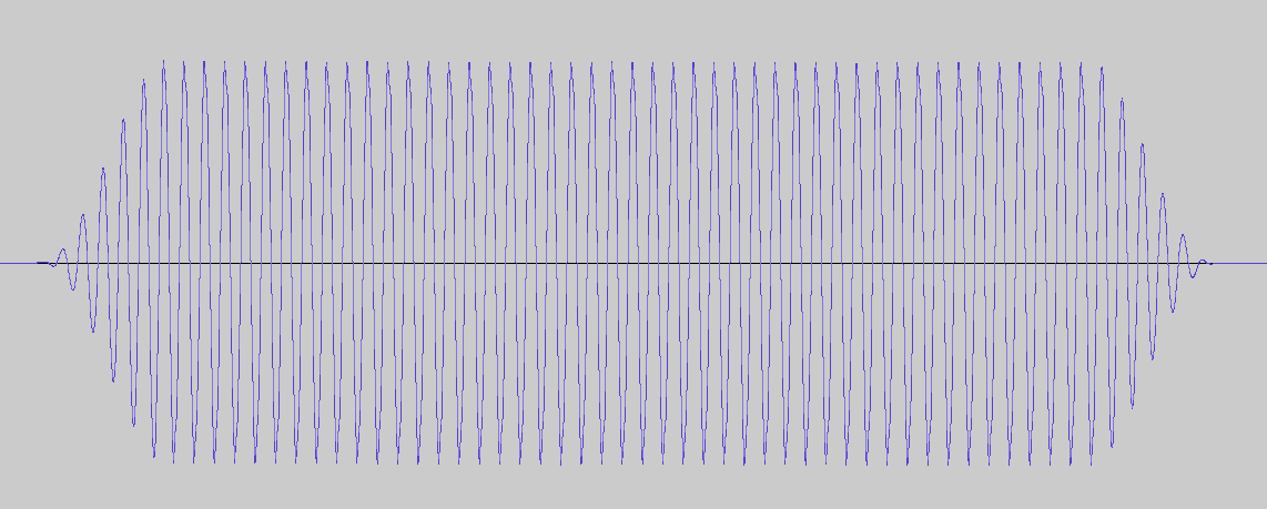
The sidetone signal is analogue captured at Fs=48kHz.
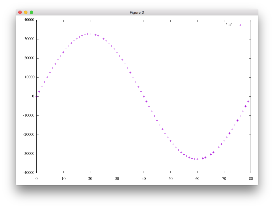
You may prefer 600Hz (=48kHz/80) to 375Hz (=48kHz/128) for sidetone. If this is the case, you divide the interval [0, 2pi] into 80 sections rather than into 128.
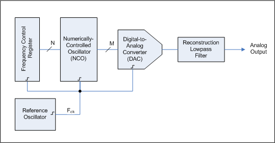
Should I use a numerically controlled oscillator (NCO) so that only a single table is required for creating a signal with arbitrary frequency?
https://en.wikipedia.org/wiki/Direct_digital_synthesizer
I do not think so.
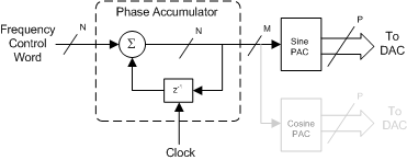
https://en.wikipedia.org/wiki/Numerically_controlled_oscillator
Phase jitter caused by truncating the phase accumulator output of N-bit into M-bit is avoidable in our situation, because only some particular frequencies, such as 607.6Hz (=48kHz/79), 600Hz (=48kHz/80), and 592.6Hz (=48kHz/81), are of our interest as far as sidetone is concerned.
Now, a sine wave.
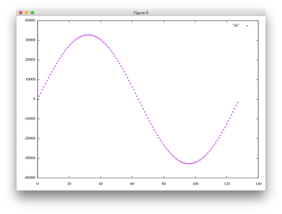
A table of 16-bit signed resolution is used with the address of 7-bit for the interval [0, 2pi].