
QSOs confirmed are much less, which I do not care very much.

Ham Radio Blog
QSOs confirmed are much less, which I do not care very much.

My first QSO with CA on 10m band. My RST was 319.
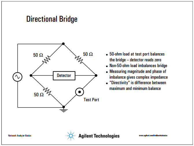
From “Network Analyzer Basics”, Agilent Technologies, slide 126.
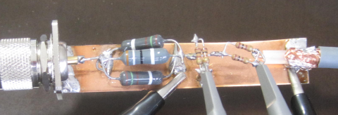
This is my directional bridge for measuring antenna impedance.


Two more nice slides from the same document.
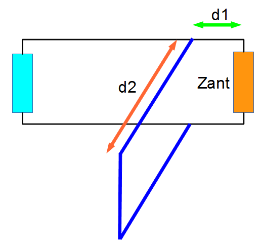

Now let’s try stub matching. The length of 75 ohm coax cables required is 531.4mm for d1 and 1182.4mm (with open end) for d2.

This is to calibrate the measurement system using a dummy load.

This is my antenna with stub matching. Looks nice. Almost as good as a dummy load.
gnuplot> load "gnuplot1.txt"
Freq [MHz]=28.001
V1=2.122
V2=2.362
Cursor 1=0.0
Cursor 2=0.0

vratio=1.11310084825636
phase1 [deg]=0.0
phase2 [deg]=0.0

abs(gamma)=0.113100848256362
swr=1.25504782146653
cz=62.7523910733263

Without stub matching, the VSWR was 2.61, so there is definitely much improvement.

The measured impedance of cz={89.9733735327047, -55.8789510601876} is traslated to the feed point impedance by using a Smith Chart.
Assuming the cable length of 20m, Zant={19.398, -8.999}.
If the cable length is 20m+10cm, then Zant={20.170, -12.965}, and if it is 20m-10cm, then Zant={18.919, -5.117}.
Parameters for stub match with 75 ohm coax cables are: 531.4mm and 1182.4mm (with open end).

First, calibration of the measurement system using a dummy load. There is almost no reflected wave (in green).

This is at 28.001MHz.
gnuplot> load "gnuplot1.txt"
Freq [MHz]=28.001
V1=2.518
V2=3.539
Cursor 1=-1e-009
Cursor 2=0.0

vratio=1.4054805401112
phase1 [deg]=-10.08036
phase2 [deg]=0.0

abs(gamma)=0.455858107934516
swr=2.67551190078067
cz={89.9733735327047, -55.8789510601876}

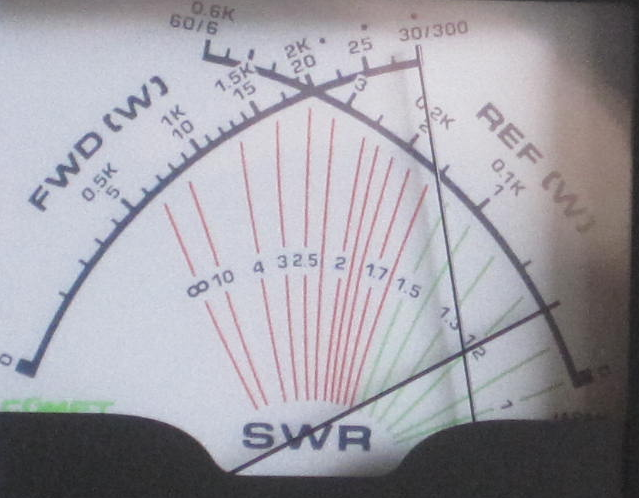
The VSWR is 2.67, and this figure matches well with the read out from a Power Meter.

The forward power is 15 W and the reflected power is 3 W. The normalized reflect voltage is sqrt(3/15)=0.4472, thus the VSWR=(1+0.4472)/(1-0.4472)=2.61.

On 10m band running 20 W, and the ANT is dipole.
Other QSOs on the band this morning are with;
N6PN, KE7X, KH7XS/W4, and LU3EHR.