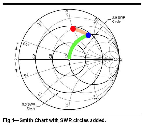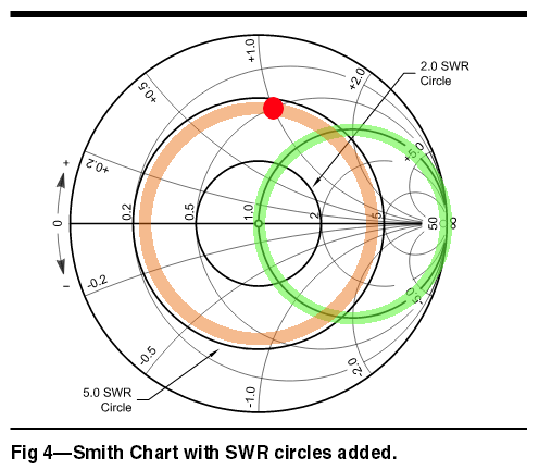
(picture from [1], but the color added by the author.)
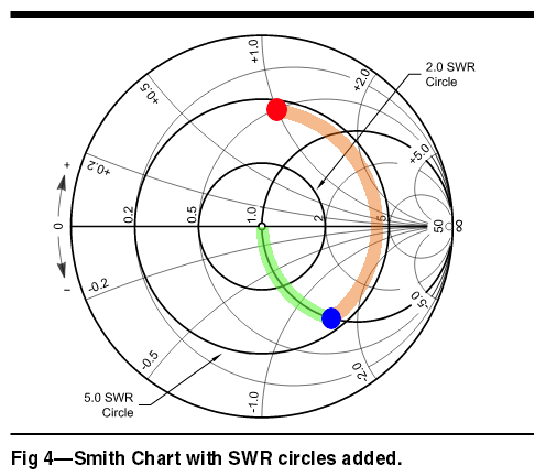
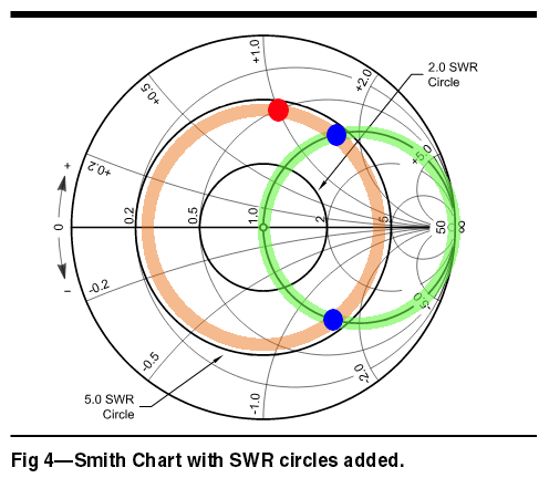
One way to solve the problem of moving from an arbitrary point to somewhere on the green circle is to use a transmission line, a coax cable, for example.
There is another family of circles called SWR circles, which means the SWR is constant anywhere on a particular circle. The SWR circles are concentric circles centered on the prime center, z=1+j0. One example is the brown circle on the chart. On the brown circle, the SWR is 4.265 everywhere.
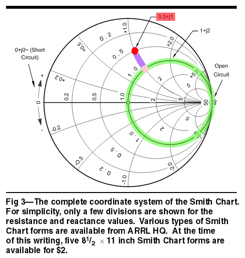
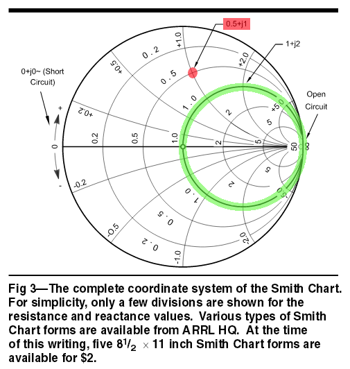
Well, the brown circle is drawn so that the red point showing your antenna impedance of Z=25+j50 [ohm], or equivalently, z=0.5+j1, is on the circle.
OK. I have an antenna, measure its impedance, put a point on a Smith Chart, and then draw a circle.
Now, watch what I do. First, the reflection coefficient, gamma:
gamma=(z-1)/(z+1)=0.07692+j0.61538.
then the absolute value of the reflection coefficient, rho:
rho=abs(gamma)=0.62017.
then the SWR, or the VSWR to be exact:
SWR=(1+rho)/(1-rho)=4.265.
[1] http://www.arrl.org/files/file/Antenna%20Book%20Supplemental%20Files/22nd%20Edition/Smith%20Chart%20Supplement%20-%20Corrected%20Jan%202012.pdf