リグ制御プログラムをpySerialで(Sメーターの読みはdBリニアか?)

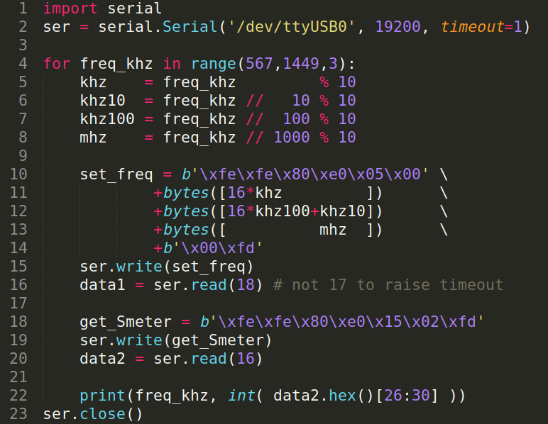
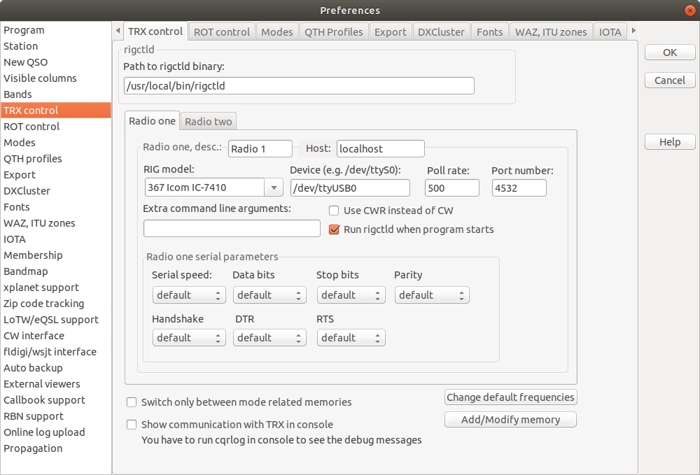
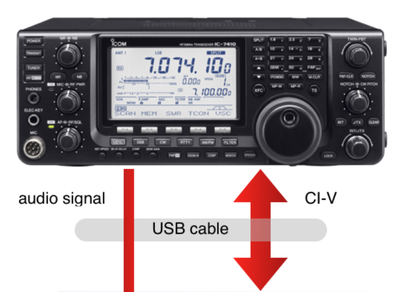
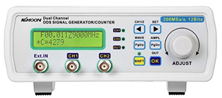
私のSGは、PCからUSBインターフェースを介して制御することができます。

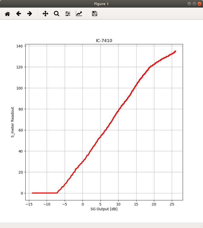
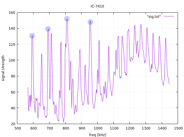
このグラフは、IC-7410のSメーターの読みを、SGの出力を0.2 Vppから20 Vppまで、20 mVppステップで変化させて示したものです。

注意: SGの出力は直接接続されているのではなくて、軽く結合されているだけです。

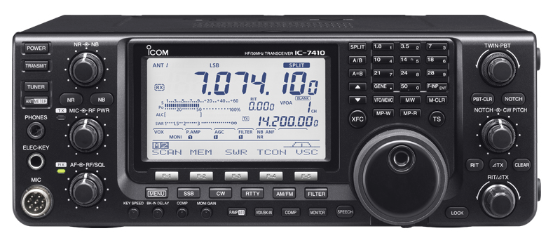
リグのマニュアルによれば、Sメーターの読みは、S0で000、 S9で120、そしてS9+60dBで240のはずです。

import sys
import math
from time import sleep
import numpy as numpy
import matplotlib.pyplot as plt
import serial

ser_sg = serial.Serial('/dev/ttyUSB0', 57600, timeout=1) # signal generator
ser_rx = serial.Serial('/dev/ttyUSB1', 19200, timeout=1) # receiver

ser_sg.write(b':\n')
s = ser_sg.read(99)
print('[:]              ', s)

ser_sg.write(b':r0c\n')
s = ser_sg.read(99)
print('[:r0c]           ', s)

ser_sg.write(b':r1c\n')
s = ser_sg.read(99)
print('[:r1c]           ', s)

ser_sg.write(b':r2c\n')
s = ser_sg.read(99)
print('[:r2c]           ', s)

ser_sg.write(b':s1f0701500000\n')
s = ser_sg.read(99)
print('[:s1f0701500000] ', s)

ser_sg.write(b':r1f\n')
s = ser_sg.read(99)
print('[r1f]            ', s)

ser_sg.write(b':s1a020\n')
s = ser_sg.read(99)
print('[s1a0123]        ', s)

ser_sg.write(b':r1a\n')
s = ser_sg.read(99)
print('[r1a]            ', s)

freq_10hz = 701500
hz10   = freq_10hz           % 10
hz100  = freq_10hz //     10 % 10
khz    = freq_10hz //    100 % 10
khz10  = freq_10hz //   1000 % 10
khz100 = freq_10hz //  10000 % 10
mhz    = freq_10hz // 100000 % 10

set_freq = b'\xfe\xfe\x80\xe0\x05'     \
		+bytes([16*hz10        ])      \
		+bytes([16*khz   +hz100])      \
		+bytes([16*khz100+khz10])      \
		+bytes([          mhz  ])      \
		+b'\x00\xfd'
ser_rx.write(set_freq)
data1 = ser_rx.read(18) # not 17 to raise timeout

xvalue = []
yvalue = []

for amp_10mv in range(20, 2002, 2):
	stramp = str(amp_10mv)
	set_amp = b':s1a'+bytes(stramp.encode())+b'\n'
	print(amp_10mv, stramp, bytes(stramp.encode()), set_amp)
	ser_sg.write(set_amp)
	sleep(0.5)
	
	get_Smeter = b'\xfe\xfe\x80\xe0\x15\x02\xfd'
	ser_rx.write(get_Smeter)
	data2 = ser_rx.read(16)
	signal = int( data2.hex()[26:30] )
	amp = amp_10mv/100.0
	ampdB = 20.0 * math.log10(amp)
	xvalue.append(ampdB)
	yvalue.append(signal)
	print(amp, ampdB, signal)

ser_sg.close()
ser_rx.close()

plt.figure(1, figsize=(8,8))
plt.subplot(111)
plt.grid(True)
plt.plot(xvalue, yvalue, color='red', linewidth=3)
plt.title('IC-7410')
plt.xlabel('SG Output [dB]')
plt.ylabel('S_meter Readout')
plt.show()

リグ制御プログラムをpySerialで(CWフィルターの特性)

信号発生器を用いて、あなたはあなたのIFフィルターの特性を測定することができます。

信号発生器の出力(7015kHzのCW)は、IC-7410に軽く結合されます。そして、信号強度が、受信部を7014kHzから7016.5kHzまで100Hz毎にチューニングされながら測定されます。

import sys
import numpy as numpy
import matplotlib.pyplot as plt
import serial

ser = serial.Serial('/dev/ttyUSB0', 19200, timeout=1)

xvalue = []
yvalue = []

for freq_10hz in range(701400, 701650, 1):
	hz10   = freq_10hz           % 10
	hz100  = freq_10hz //     10 % 10
	khz    = freq_10hz //    100 % 10
	khz10  = freq_10hz //   1000 % 10
	khz100 = freq_10hz //  10000 % 10
	mhz    = freq_10hz // 100000 % 10

	set_freq = b'\xfe\xfe\x80\xe0\x05'     \
			+bytes([16*hz10        ])      \
			+bytes([16*khz   +hz100])      \
			+bytes([16*khz100+khz10])      \
			+bytes([          mhz  ])      \
			+b'\x00\xfd'
	ser.write(set_freq)
	data1 = ser.read(18) # not 17 to raise timeout
	
	get_Smeter = b'\xfe\xfe\x80\xe0\x15\x02\xfd'
	ser.write(get_Smeter)
	data2 = ser.read(16)
	signal = int( data2.hex()[26:30] )
	freq = freq_10hz/100.0
	xvalue.append(freq)
	yvalue.append(signal)
	print(freq, signal)

ser.close()

plt.figure(1, figsize=(8,8))
plt.subplot(111)
plt.grid(True)
plt.plot(xvalue, yvalue, color='red', linewidth=3)
plt.show()

受信部は、それぞれがプリセット可能な3種類のディジタルIFフィルターを備えています。グラフは、私の現在の設定を示しています。

リグ制御プログラムをpySerialで

リグを制御するプログラムをpySerialを用いて書いてみましょう。

import serial
ser = serial.Serial('/dev/ttyUSB0', 19200, timeout=1)

for freq_khz in range(567,1449,3):
	khz    = freq_khz         % 10
	khz10  = freq_khz //   10 % 10
	khz100 = freq_khz //  100 % 10
	mhz    = freq_khz // 1000 % 10

	set_freq = b'\xfe\xfe\x80\xe0\x05\x00' \
			+bytes([16*khz         ])      \
			+bytes([16*khz100+khz10])      \
			+bytes([          mhz  ])      \
			+b'\x00\xfd'
	ser.write(set_freq)
	data1 = ser.read(18) # not 17 to raise timeout
	
	get_Smeter = b'\xfe\xfe\x80\xe0\x15\x02\xfd'
	ser.write(get_Smeter)
	data2 = ser.read(16)

	print(freq_khz, int( data2.hex()[26:30] ))
ser.close()

簡単なプログラムで、AMバンドをスキャンして信号強度を記録します。

放送局は、左から右へ、NHK-1, NHK-2, AFN, TBSです。

7MHz受信用のスモールループアンテナ作成(2)

ポリバリコンのセクションC1とC2とを並列に用いた場合、このアンテナは4.030MHzから9.860MHzの範囲で同調可能でした。これは、以下の表から予想される通りです。

ポリバリコンの各セクションの容量の実測値
       min       center	     max
----------------------------------
c1  148.4pF      62.6pF    22.0pF
c2  150.3pF      65.9pF    23.5pF
c3   40.7pF      27.8pF    19.9pF
c4   40.4pF      26.9pF    19.8pF
L=5.1uHの時の、容量のあるべき値:
 3.5MHz   7MHz  10MHz  14MHz  18MHz  21MHz  25MHz  28MHz
-------------------------------------------------------
  405pF  101pF   50pF  25pF   15pF    11pF    8pF    6pF

7MHz受信用のスモールループアンテナ作成

初めてのスモールループアンテナです。スモールというのは、ループの周長が動作する波長の1/10程度であることをいいます。

私は、40m帯でアンテナを使いたかったので、TV用の古い同軸ケーブルを4.5mに切って、編組のみを使いました。ループの形はほとんど何でも良いのですが、私は3角形にしました。木で作ったT字型の枠がループを保持するように。

4.5m長のループのインダクタンスは測定した所、5.1uHでした。従って、100pFのコンデンサで7MHzに同調するはずです。

私は、AM/FMラジオ用のポリバリコンを使いました。4つのセクションから成り、 160pF x 2と40pF x 2です。実験は、2つの160pFのセクションを並列に用いることから始めました。

カップラーは、1回巻き対8回巻きのFT-140-43を用いたトロイダルコアのトランスです。

これが、結果です。共振は非常にシャープなので、周波数を振るのが荒いと容易に同調点を見逃してしまいます。

最初の試みにしては悪くないですね。。

まだアンテナが室内にある状態で、FT8で受信できた局の一部です。

元統合参謀本部議長は懸念している・・

https://edition.cnn.com/videos/tv/2018/04/06/exp-gps-0408-mullen-sot-generals.cnn

Former Joint Chiefs chairman worries about generals in Trump’s White House
(元統合参謀本部議長の一人は、トランプのホワイトハウスで働く将軍たちの存在を懸念している)
By Kate Sullivan
Updated 6:17 PM ET, Sun April 8, 2018

(CNN) — Retired Adm. Mike Mullen, a former chairman of the Joint Chiefs of Staff under Presidents George W. Bush and Barack Obama, said Sunday on CNN’s “Fareed Zakaria GPS” that he has been “extremely concerned” about military officials like retired Gen. John Kelly acting in political roles in President Donald Trump’s administration.

Mullen said he worries that having military officials, “without being a politician, without running for office,” acting politically could undermine the military as an apolitical institution.

Specifically, he said, he worries a “great deal” about Kelly “indirectly undermining us as a military” because of his role as White House chief of staff, a highly political job.

While many people have told him they have felt comfortable having Secretary of Defense James Mattis, Kelly, and former White House national security adviser H.R. McMaster in Trump’s administration, all of whom have been generals, “I don’t share that comfort,” Mullen said.

Mullen said he’s been to countries where the generals and admirals are in charge, which some of the public find comforting, and those are not countries Americans would want to grow up in.

“It’s much more a strongman’s country than it is a democratic, open, free country,” he said.

Mattis, Kelly and McMaster “are not politicians, but they’re operating in this political world inside the White House,” said Mullen, who served four years under two presidents, adding he understands that world well.

“It is a tough, difficult, political environment,” he said, and “it can be very toxic, and it can destroy people.”

McMaster was recently ousted as Trump’s national security adviser; his last day at the White House was Friday. Meanwhile, CNN has reported on tensions between the President and Kelly, who has become the subject of reports saying his influence in the White House is diminished. Trump on Sunday denied that was the case in a tweet criticizing The Washington Post’s reporting on the matter.

Mullen added that he was distressed to see Kelly, a retired four-star general, talk to the press about his experience with the death of his son in Afghanistan as part of an attempt to counter criticisms of Trump’s conversation with a widow of a soldier killed in an ISIS ambush in Niger last year.


“To see John Kelly — and I’ll be very specific — politicize, you know, the death of his son to support the political outcome for the President was very, very distressing to me,”
(強調は引用者による) Mullen said.

It speaks to the power of that environment, he said, and “the lack of understanding that any of us in the military have about that environment until we get in it and have to operate in it.”

“We are apolitical,” Mullen said about his fellow military service members. “I get that when we take our uniform off we’re citizens,” he added, but “he’s referred to as General Kelly, not Mr. Kelly, for a reason.”

WSJT-Xと、CQRLog

どちらもリグを制御するのにrigctldを使うことができるので、これらのプログラムを同時に用いる場合のセットアップ方法の1つは、CQRLogrigctldを起動させて、 WSJT-Xにそれを使わせることです。

WSJT-XとQt

WSJT-XのGUIは、C++で書かれQtフレームワークを用いています。

それで、私も自分でQtフレームワークを使ってみると面白いかなと思いました。そして、私の昔のプログラム、例えば、sprigmmを、QtのAPIで書き直してみようかと。

Ubuntu 17.10では、あなたはexamplesが表示されないとか、

ビルドエラー: cannot find -lGLに出くわすかもしれません。

USBオーディオインターフェース付きのリグとLinuxサウンドシステム(Audacity)

Audacityを用いて、あなたはUSBインターフェースを介して、あなたのリグから/へ録音と再生をすることができます。

もし、あなたのリグがIC-7410であれば、セットモードに入って以下のようにして下さい。

  • 39. USB MOD Level: 50% (as default)
  • 40. DATA OFF MOD: USB
  • 41. DATA MOD: USB

オーディオデバイスのリストが、Audacityのメニューバー、Help -> Audio Device Info..から得られます。

==============================
Device ID: 8
Device name: USB Audio CODEC: - (hw:2,0)
Host name: ALSA
Recording channels: 2
Playback channels: 2
Low Recording Latency: 0.00868
Low Playback Latency: 0.008685
High Recording Latency: 0.034830
High Playback Latency: 0.034830
Supported Rates:
    32000
    44100
    48000
==============================
Selected recording device: 8 - USB Audio CODEC: - (hw:2,0)
Selected playback device: 8 - USB Audio CODEC: - (hw:2,0)
Supported Rates:
    32000
    44100
    48000

ディレクトリ、 /proc/asound、からは、より詳細な情報を得ることができます。

user1@Asrock ~ % ls -l /proc/asound/card2  
total 0
-r--r--r-- 1 root root 0 Apr  5 12:05 id
dr-xr-xr-x 3 root root 0 Apr  5 12:05 pcm0c
dr-xr-xr-x 3 root root 0 Apr  5 12:05 pcm0p
-r--r--r-- 1 root root 0 Apr  5 12:05 stream0
-r--r--r-- 1 root root 0 Apr  5 12:05 usbbus
-r--r--r-- 1 root root 0 Apr  5 12:05 usbid
-r--r--r-- 1 root root 0 Apr  5 12:05 usbmixer

user1@Asrock ~ % ls -l /proc/asound/card2/pcm0c/sub0
total 0
-r--r--r-- 1 root root 0 Apr  5 12:06 hw_params
-r--r--r-- 1 root root 0 Apr  5 12:06 info
-r--r--r-- 1 root root 0 Apr  5 12:06 status
-r--r--r-- 1 root root 0 Apr  5 12:06 sw_params

user1@Asrock ~ % cat /proc/asound/card2/pcm0c/sub0/info
card: 2
device: 0
subdevice: 0
stream: CAPTURE
id: USB Audio
name: USB Audio
subname: subdevice #0
class: 0
subclass: 0
subdevices_count: 1
subdevices_avail: 1

user1@Asrock ~ % cat /proc/asound/card2/pcm0c/sub0/status
state: RUNNING
owner_pid   : 3672
trigger_time: 3005.885223991
tstamp      : 3010.659571001
delay       : 240
avail       : 240
avail_max   : 240
-----
hw_ptr      : 229442
appl_ptr    : 229202

user1@Asrock ~ % cat /proc/asound/card2/pcm0c/sub0/hw_params 
access: MMAP_INTERLEAVED
format: S16_LE
subformat: STD
channels: 1
rate: 48000 (48000/1)
period_size: 1200
buffer_size: 6000

user1@Asrock ~ % cat /proc/asound/card2/pcm0c/sub0/sw_params 
tstamp_mode: ENABLE
period_step: 1
avail_min: 1200
start_threshold: 1200
stop_threshold: 6000
silence_threshold: 0
silence_size: 6755399441055744000
boundary: 6755399441055744000

もし、Project Rate (Hz):を、48000から44100に変更すると、以下のようになります。>

user1@Asrock ~ % cat /proc/asound/card2/pcm0c/sub0/hw_params
access: MMAP_INTERLEAVED
format: S16_LE
subformat: STD
channels: 1
rate: 44100 (44100/1)
period_size: 1102
buffer_size: 5510

あなたのPCクロックをUTCに同期させる

ある種のアプリケーション、例えば、WSJT-X、では、あなたのPCクロックをUTCに±1秒以内に合わせることが要求されます。

NICTはNTPサーバー、ntp.nict.jp、を公開しています。以下は、Linuxマシンでこのサービスを利用する方法の1つです。

最近のUbuntu(16.04、及び以降)では、timedatectl / timesyncd(これは、systemdの一部です)が、ntpdate / ntpを置き換えています。

user1@Asrock ~ % timedatectl status                   
      Local time: Wed 2018-04-04 08:44:25 JST
  Universal time: Tue 2018-04-03 23:44:25 UTC
        RTC time: Tue 2018-04-03 23:44:25
       Time zone: Asia/Tokyo (JST, +0900)
 Network time on: yes
NTP synchronized: yes
 RTC in local TZ: no

これは、現在の時刻と時計の構成状況を示しています。時刻を取得するためのNTPサーバーは、/etc/systemd/timesyncd.confで指定します。

/etc/systemd/timesyncd.conf

[Time]
NTP=ntp.nict.jp
FallbackNTP=ntp.jst.mfeed.ad.jp

user1@Asrock ~ % sudo systemctl -l status systemd-timesyncd
● systemd-timesyncd.service - Network Time Synchronization
   Loaded: loaded (/lib/systemd/system/systemd-timesyncd.service; enabled; vendor preset: enabled)
   Active: active (running) since Wed 2018-04-04 06:40:05 JST; 1h 42min ago
     Docs: man:systemd-timesyncd.service(8)
 Main PID: 800 (systemd-timesyn)
   Status: "Synchronized to time server [2001:df0:232:eea0::fff3]:123 (ntp.nict.jp)."
    Tasks: 2 (limit: 4915)
   Memory: 1.7M
      CPU: 31ms
   CGroup: /system.slice/systemd-timesyncd.service
           └─800 /lib/systemd/systemd-timesyncd

Apr 04 06:40:05 Asrock systemd[1]: Starting Network Time Synchronization...
Apr 04 06:40:05 Asrock systemd[1]: Started Network Time Synchronization.
Apr 04 06:40:35 Asrock systemd-timesyncd[800]: Synchronized to time server [2001:df0:232:eea0::fff3]:123 (ntp.nict.jp).

macOSでは、あなたはNTPサーバーを、System Preferences -> Date & Timeで、変更できます。